
LDO circuit using bidirectional asymmetry buffer structure to improve performance

A buffer and asymmetric technology, applied in the direction of instruments, adjusting electrical variables, control/regulation systems, etc., can solve the problems of reducing LDO power supply voltage rejection ratio, increasing LDO quiescent current, increasing circuit complexity, etc., to improve transient Response performance, expansion of unity gain bandwidth, flexible circuit configuration and various effects

Inactive Publication Date: 2008-10-08
BEIJING MXTRONICS CORP +2
View PDF0 Cites 19 Cited by
  • Summary
  • Abstract
  • Description
  • Claims
  • Application Information

AI Technical Summary

Problems solved by technology

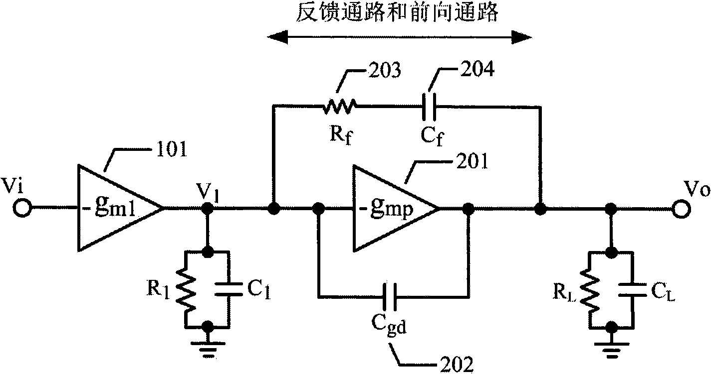
Therefore, this circuit does not eliminate the right-half-plane zero ω ZRHP
In addition, the circuit also has the following disadvantages: the capacitive load driving ability is weak, and a large compensation capacitor C is required f , thereby increasing the chip area, reducing the slew rate and transient response speed of internal nodes; reducing the power supply rejection ratio (Power Supply Rejection Ratio, PSRR) performance of the LDO
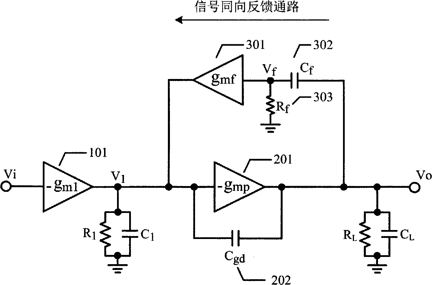
However, this right-half-plane zero cancellation mechanism based on the forward transconductance stage has the following disadvantages: First, the forward transconductance stage can only provide the forward path, so the feedback compensation mechanism cannot be realized
For this reason, it is necessary to add an additional feedback compensation circuit, which increases the complexity of the circuit and may lead to a reduction in response speed and PSRR performance; secondly, the forward transconductance stage 301 increases the complexity of the circuit and introduces an additional offset voltage, and increases the parasitic capacitance at the input of the gain stage 101; more importantly, the forward transconductance stage is suitable for applications where the output stage is a Push-Pull or Class-AB structure
In the LDO circuit, the output stage is a transmission element, so the introduction of the forward transconductance stage increases the quiescent current of the LDO, which is not conducive to low power consumption design

Method used


Image

  • LDO circuit using bidirectional asymmetry buffer structure to improve performance
  • LDO circuit using bidirectional asymmetry buffer structure to improve performance
  • LDO circuit using bidirectional asymmetry buffer structure to improve performance

Examples


Embodiment Construction

[0047] Figure 5 A block diagram of the circuit for canceling the right-half-plane zero point of the present invention is given, including the buffer stage 401, the first inverse gain stage 101, the LDO transfer element 201, and the gate-to-drain parasitic capacitance C of the LDO transfer element 201 gd 202, and by the second inverting gain stage 301, capacitor C f 302, resistance R f 303 bidirectional asymmetric buffer structure. Node V i , V b , V 2 and V o are respectively the input end of the buffer stage 401, the output end, the output end of the first inverting gain stage 101, and the output end of the LDO, R b 、C b for node V b The output impedance and lumped parasitic capacitance, R 2 、C 2 for node V 2 The output impedance and lumped parasitic capacitance, R L 、C L for node V o output impedance (including load impedance) and load capacitance.

[0048] It should be noted, Figure 5 The buffer stage 401 in the shown functional block diagram may be a b...


PUM


Abstract

A LDO circuit using two-way asymmetry buffer mechanism to improve performance. The two-way asymmetry buffer mechanism is adopted, at the same time, a feedback circuit with signal back function and a forward passage with signal direct function are adopted; the feedback circuit is used for realizing a frequency compensation of the LDO circuit and improving temporal response performance; the forward circuit is used for counteracting a right half-plane zero point generated by a grid leak parasitic capacitance of a LDO transfer component so as to improve the stability of the system and gain bandwidth of an expanded unit. This circuit has advantages of simple structure, low energy consumption, and effectively removing the right half-plane zero point.

Description

technical field [0001] The invention relates to an LDO circuit, in particular to an LDO circuit which utilizes a bidirectional asymmetric buffer structure to effectively eliminate the right-half-plane zero point in a low-dropout linear regulator, thereby enhancing loop stability and improving system performance. Background technique [0002] Closed-loop negative feedback systems are often used in linear circuits. For example, in a low-dropout voltage regulator (LDO, Low-Dropout Voltage Regulator), a stable output voltage is obtained by using a feedback loop. In order to reduce the input-output voltage difference (Dropout voltage) and enhance the current drive capability, the transmission element in the LDO (also known as transmission tube, adjustment tube, power tube, Pass Element, Power Device, etc.) usually has a very large width-to-length ratio ( Such as 20000μm / 1μm), so its gate-drain parasitic capacitance C gd Usually large (such as 10pF). Parasitic capacitance C gd...

Claims


Application Information

Patent Timeline
IPC IPC(8): G05F1/56
Inventor 沈良国严祖树赵元富张兴
Owner BEIJING MXTRONICS CORP
Learn More