Wide band high voltage intelligent electric resistance partial pressure type voltage sensor
A technology of voltage sensor and resistor voltage division, applied in the direction of inductors, transformers, voltage/current isolation, etc., to achieve low temperature drift, easy calibration, and wide test range
- Summary
- Abstract
- Description
- Claims
- Application Information
AI Technical Summary
Problems solved by technology
Method used
Image
Examples
Embodiment 1
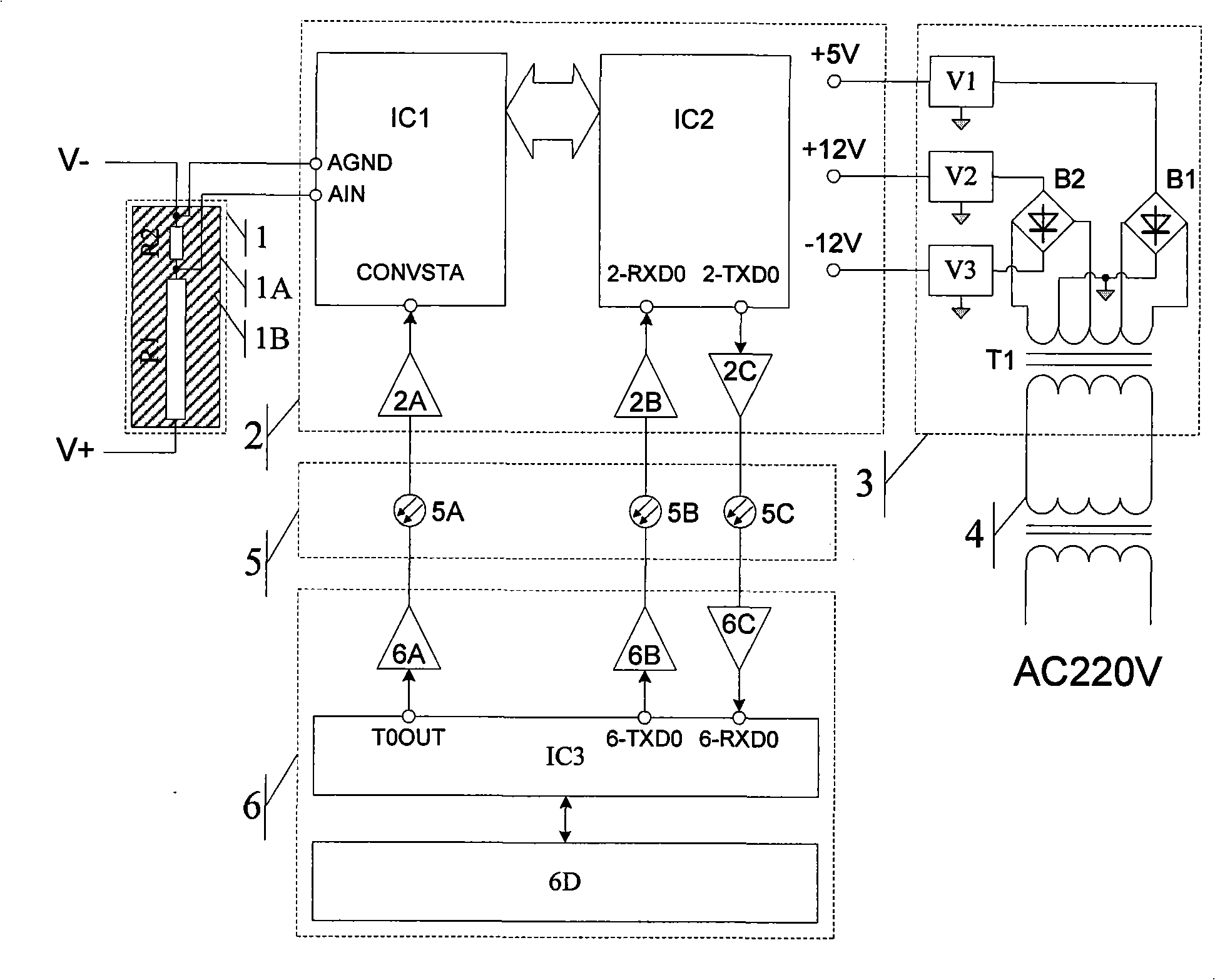
[0023] Embodiment 1: refer to figure 1 and figure 2 :
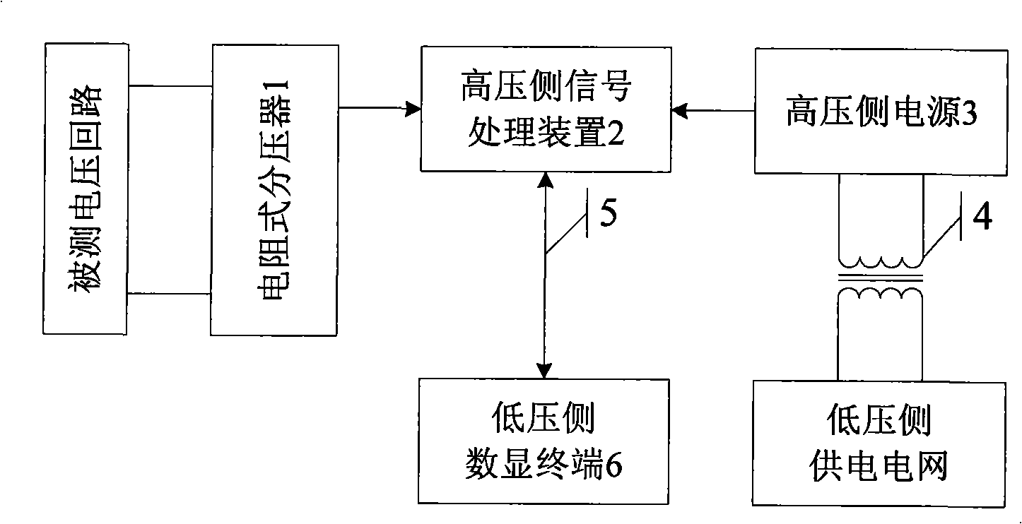
[0024] This embodiment includes a resistive voltage divider (1) for extracting voltage signals from the measured voltage circuit, a high-voltage side signal processing device (2), a high-voltage side power supply (3), a high-voltage isolation transformer (4), and a communication optical fiber group ( 5), the digital display terminal (6) on the low-voltage side.
[0025] In this embodiment, the low-voltage side power supply grid adopts AC220V mains power.
[0026] The resistive voltage divider (1) is used as a voltage sensing device, and the analog voltage signal after the voltage division of the measured voltage signal connected to both ends of V+ and V- is connected to the high-voltage side signal processing device (2), and the high-voltage side signal processing device ( 2) Convert the analog voltage signal output by the resistive voltage divider (1) into a digital signal and upload it to the digital display termina...
Embodiment 2
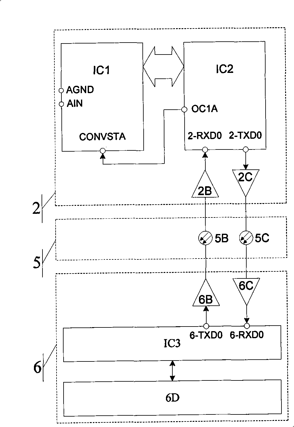
[0036] Refer to attached image 3 : (The figure omits the connection with figure 2 The same resistive voltage divider 1, high-voltage side power supply 3, and high-voltage isolation transformer 4) in the same embodiment, the difference between this embodiment and embodiment 1 is that the wide-band high-voltage intelligent resistor divider voltage sensor in this embodiment does not care about the measured signal Sampling time, that is, no need for synchronous sampling or phase comparison with other signals, the high-voltage side signal processing device (2) saves the sampling clock receiver 2A, the communication fiber group (5) saves the communication fiber 5A, and the low-voltage side digital display The terminal (6) omits the sampling clock transmitter 6A, and simultaneously connects the A / D conversion start signal CONVSTA of the A / D converter IC1 directly to the clock output pin OC1A of the microprocessor IC2, and IC2 provides the sampling clock signal.
Embodiment 3
[0038] Refer to attached Figure 4 : (The figure omits the connection with figure 2 The same resistive voltage divider 1, high-voltage side power supply 3, and high-voltage isolation transformer 4) in the same embodiment, the difference between this embodiment and embodiment 1 is that in this embodiment, the broadband high-voltage intelligent resistance divider voltage sensor does not need to set various instructions , the solid high-voltage side signal processing device (2) can save the serial data receiver 2B, the communication fiber group (5) can save the communication fiber 5B, and the low-voltage side digital display terminal (6) can save the serial data transmitter 6B .
PUM
 Abstract
Description
Claims
Application Information
 - R&D
- Intellectual Property
- Life Sciences
- Materials
- Tech Scout
- Unparalleled Data Quality
- Higher Quality Content
- 60% Fewer Hallucinations
Browse by: Latest US Patents, China's latest patents, Technical Efficacy Thesaurus, Application Domain, Technology Topic, Popular Technical Reports.
© 2025 PatSnap. All rights reserved.Legal|Privacy policy|Modern Slavery Act Transparency Statement|Sitemap|About US| Contact US: help@patsnap.com


