
LED apparatus

A technology of light-emitting diodes and light-emitting layers, which is applied to electrical components, electric solid-state devices, circuits, etc., can solve problems such as heat accumulation, current embolism at junctions, and difficulty in uniform diffusion of current, so as to improve dissipation efficiency and avoid current embolism. Effect

Inactive Publication Date: 2008-10-15
DELTA ELECTRONICS INC
View PDF0 Cites 17 Cited by
  • Summary
  • Abstract
  • Description
  • Claims
  • Application Information

AI Technical Summary

Problems solved by technology

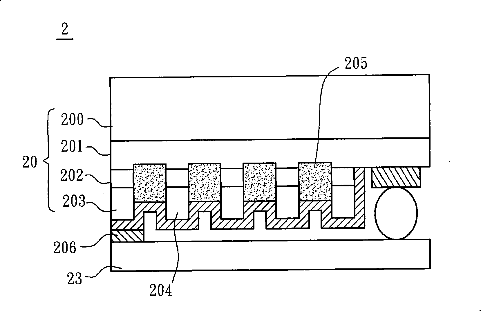
However, since the material of the reflective layer 206 is mostly selected from metal materials, there is a phenomenon of high Schottky barrier (Schotty barrier) at the junction formed between it and the second semiconductor layer 203, causing the resistance value to be too high to make the current flow difficult. Uniform diffusion, that is, a current embolism is caused at the junction, which further increases the operating voltage of the LED device 2, and the resulting heat accumulation also causes more serious heat dissipation problems because there is no path to conduct to the outside world.

Method used


Image

  • LED apparatus
  • LED apparatus
  • LED apparatus

Examples


Embodiment Construction

[0032] A light emitting diode device according to a preferred embodiment of the present invention will be described below with reference to related figures.

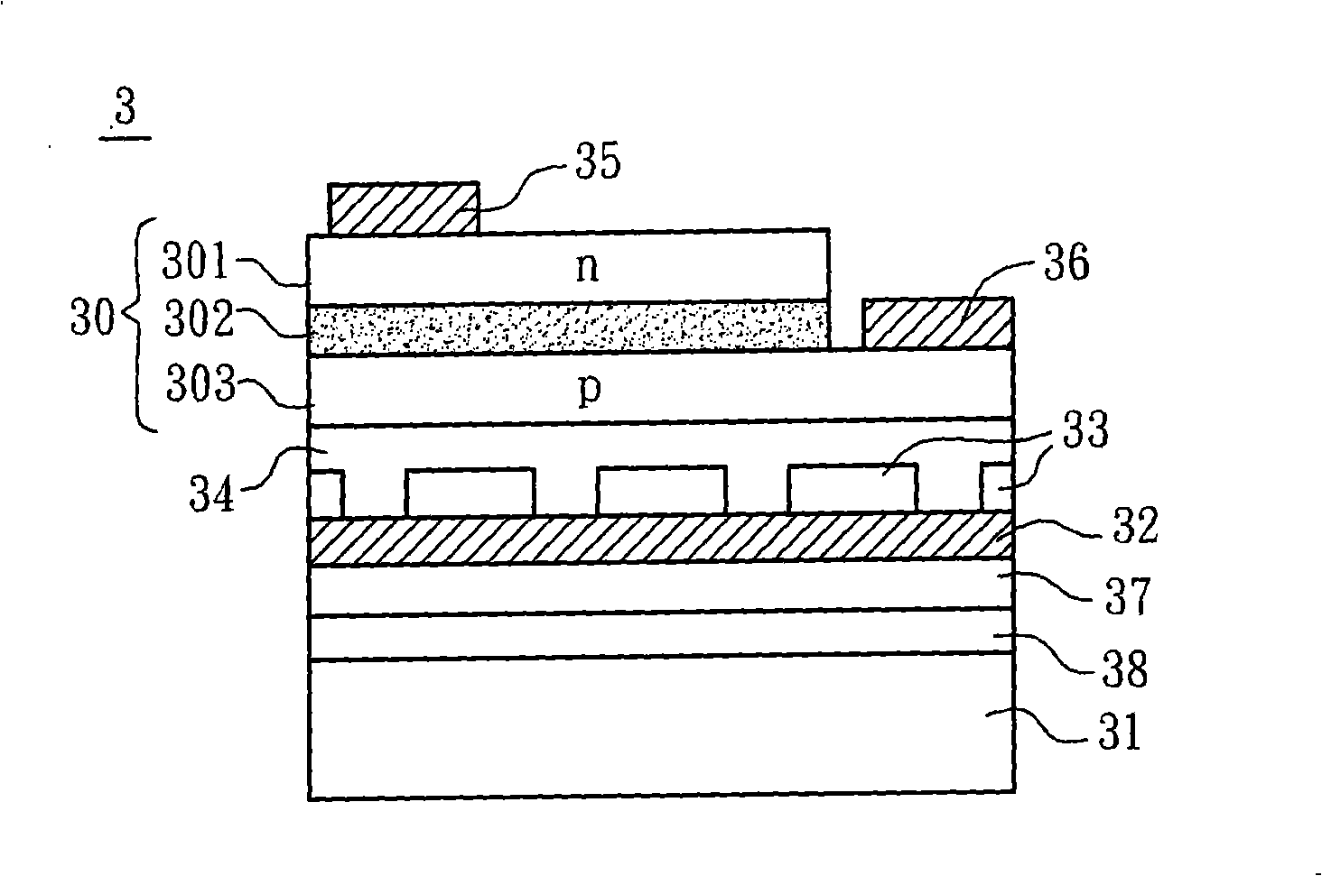
[0033] Please refer to image 3 As shown, a light emitting diode device 3 according to a preferred embodiment of the present invention includes a heat dissipation substrate 31 , a sandwich structure S, an epitaxial stack 30 , a first contact electrode 35 and a second contact electrode 36 .

[0034] The heat dissipation substrate 31 is a permanent substrate with a high thermal conductivity, and depending on the material, the heat dissipation substrate 31 can be a heat dissipation substrate of a metal material, a heat dissipation substrate of a composite material, or a heat dissipation substrate of an insulating material. In this embodiment, the material of the heat dissipation substrate 31 can be selected from the group consisting of aluminum, copper, aluminum copper oxide, silicon, gallium arsenide, gallium phosphide, si...


PUM


Abstract

The invention discloses a light emitting diode (LED) device which includes a heat-dissipating baseplate, a sandwich structure, an epitaxial lamination, a first contact electrode and a second contact electrode, wherein, the sandwich structure includes a reflecting layer, a patterning insulated heat conducting layer and a transparent conducting layer, and the patterning insulated heat conducting layer is arranged between the reflecting layer and the transparent conducting layer. The sandwich structure is positioned between the heat-dissipating baseplate and the epitaxial lamination so as to lead current to be centralized to flow to the reflecting layer or the transparent conducing layer and then be diffused evenly by the transparent conducting layer. The epitaxial lamination includes a first semiconductor layer, a luminous layer and a second semiconductor layer, wherein, the first contact electrode is electrically connected with the first semiconductor layer, while the second contact electrode is electrically connected with the second semiconductor layer.

Description

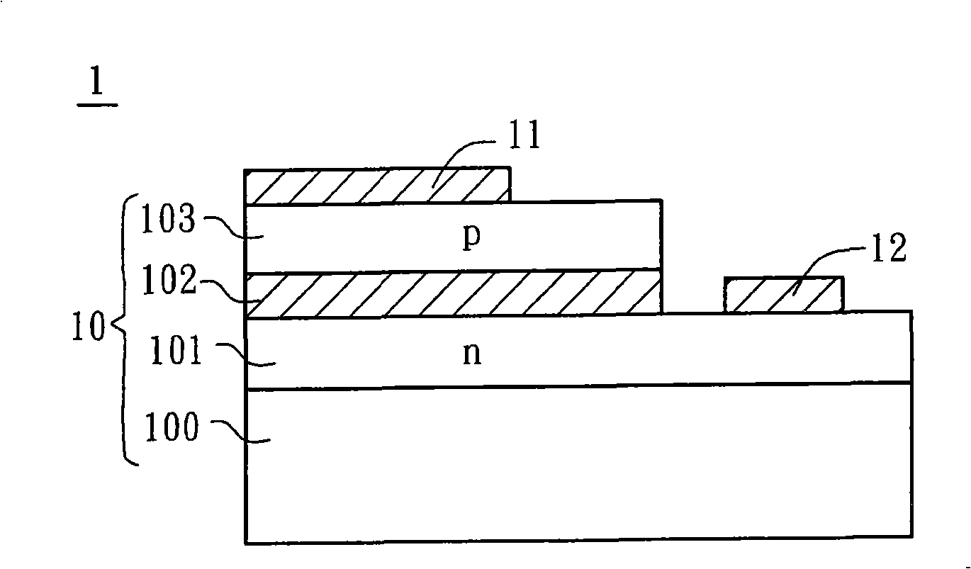
technical field [0001] The invention relates to an electroluminescent device, in particular to a light emitting diode device. Background technique [0002] A light emitting diode (Light Emitting Diode, LED) is a kind of luminescent light-emitting element, which utilizes the energy released by the combination of electrons and holes in a semiconductor material, and releases it in the form of light. Depending on the material used, it can emit monochromatic light of different wavelengths. It can be mainly divided into two types: visible light-emitting diodes and invisible light (infrared) light-emitting diodes. Compared with traditional light bulbs, light-emitting diodes have the advantages of power saving, shock resistance and fast flashing speed, so they become indispensable in daily life. important components. [0003] Please refer to figure 1 , a known light emitting diode element 10 includes an epitaxial substrate 100 , a first semiconductor layer 101 , a light emitting ...

Claims


Application Information

Patent Timeline
Patent Type & Authority Applications(China)
IPC IPC(8): H01L33/00H01L23/36H01L33/40H01L33/64
CPCH01L2224/16
Inventor 薛清全陈世鹏陈朝旻陈煌坤
Owner DELTA ELECTRONICS INC
Learn More