
System for realizing subnet dependent converge protocol

A technology of aggregation protocols and subnets, applied in the field of communication, to achieve the effect of reasonable logic, improved overall performance, and fast and simple implementation methods

Inactive Publication Date: 2008-10-15
ZTE CORP
View PDF0 Cites 9 Cited by
  • Summary
  • Abstract
  • Description
  • Claims
  • Application Information

AI Technical Summary

Problems solved by technology

[0008] However, there is currently no method to quickly and accurately implement SNDCP to achieve fast and accurate data transmission

Method used


Image

  • System for realizing subnet dependent converge protocol
  • System for realizing subnet dependent converge protocol
  • System for realizing subnet dependent converge protocol

Examples


Embodiment 1

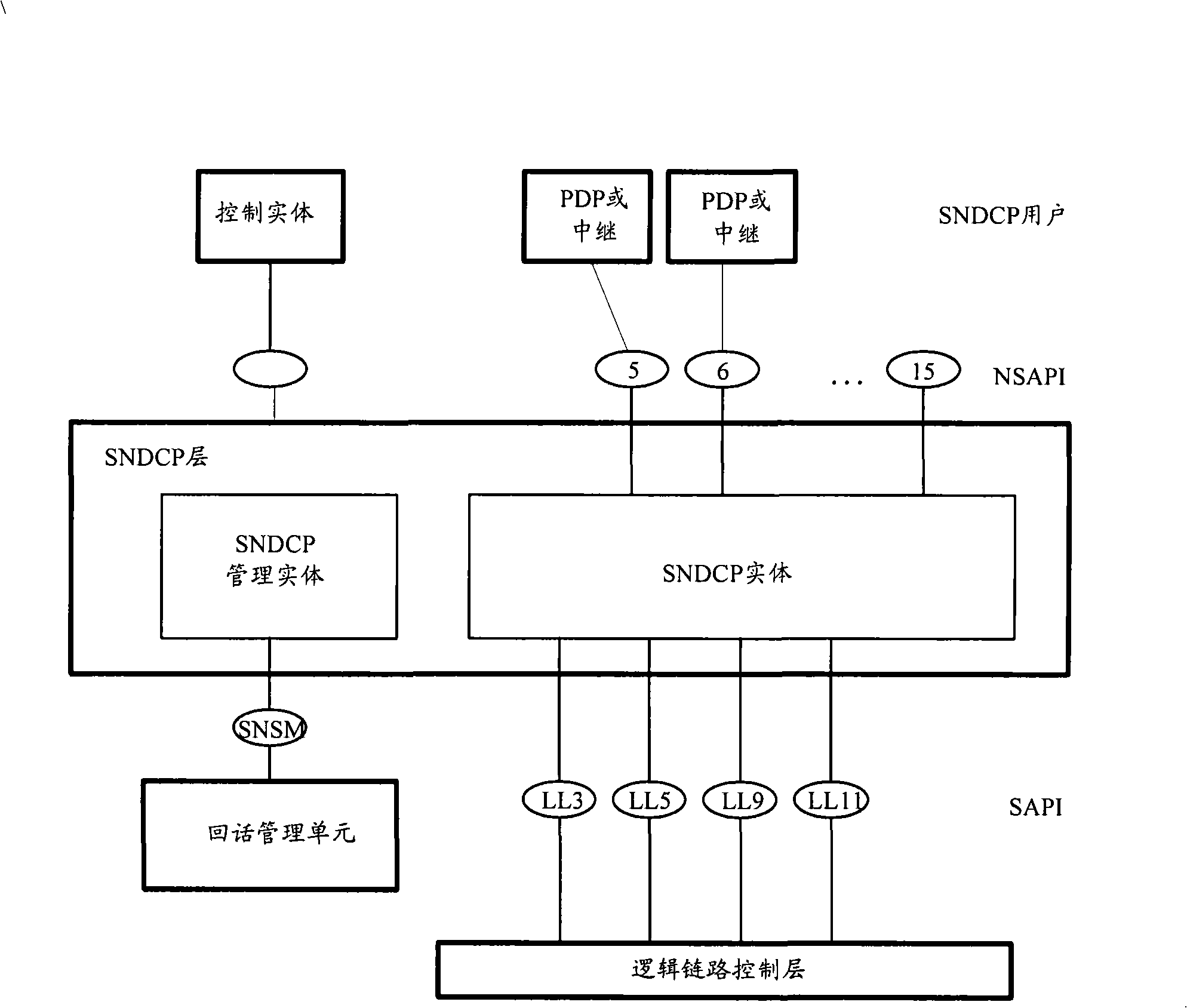
[0036] Such as Figure 5 As shown, the SNDCP module is initialized after being called by the OS, and the SAPI instance enters the IDLE state. The specific implementation process includes the following steps:

[0037] S502, the MMIA notifies SNDCP of the compression algorithm configured through the AT command through the SN_XID_REQ message;

[0038] S504, SM notifies SNDCP through SNSM_ACTIVATE_IND that the current PDP context has been activated, and a logical link needs to be established for the specified NSAPI;

[0039] S508, SNDCP confirms according to the reliability level of the NSAPI. If it is an NSAPI in confirmation mode, and the SAPI mapped to the NSAPI has not established a confirmation peer LLC logical link, then a logical link is established by sending a LL_ESTABLISH_REQ request to the LLC layer, At the same time, the SAPI instance enters the WAIT_EST state;

[0040] S510, SNDCP receives the LL_ESTABLISH_CNF message sent by the LLC layer, indicating that the logic...

Embodiment 2

[0044] Such as Figure 6 As shown, when the PDP context is deactivated, the specific implementation process includes the following steps:

[0045] S602, the SM instructs the SNDCP that the NSAPI has been deactivated through the SNSM_DEACTIVATE_IND message, instructs the SNDCP to release the logical link, and the SNDCP management module enters the SAPI instance for processing.

[0046] S604. If the SAPI mapped on the NSAPI has no other confirmation mode NSAPI using the logical link, the SNDCP sends LL_RELEASE_REQ to release the logical link, and enters the WAIT_RLS state through the SAPI instance.

[0047] S606, SNDCP receives the LL_RELEASE_CNF sent by the LLC layer, indicating that the logical link has been released. At this time, the SAPI instance returns to the IDLE state. In this state, if there is an activated NSAPI, non-confirmed data transmission can still be performed.

[0048] S608, the SNDCP responds to the SM through SNSM_DEACTIVATE_RSP, indicating that the logical...


PUM


Abstract

The invention discloses a system for realizing sub network dependent convergence protocol, which comprises a module initiation unit, a module mapping unit, a data processing module, a data resolving unit and a data transmitting unit, wherein, the module initiation unit is used for establishing a protocol management module and a plurality of SAPI examples when modules are initialized, and establishing a logical link for the SAPI examples; the module mapping unit is used for establishing NSAPI examples and establishing the logical link for the NSAPI examples when receiving activation indication, establishing mapping relationship between the SAPI examples and the NSAPI examples and storing the mapping relationship between the SAPI examples and one or more NSAPI examples in the protocol management module; the data processing module is used for compressing a first data packet from an application layer and dividing the compressed first data packet into a plurality of parts; the data resolving unit is used for resolving the SAPI examples which corresponds to and is used for identifying the NSAPI examples of the data packet from the application layer from the first data packet; the data transmitting unit is used for transmitting a plurality of parts of the compressed first data packet to a peer layer by the logical link of the SAPI examples which corresponds to and is used for identifying the NSAPI examples of the first data packet.

Description

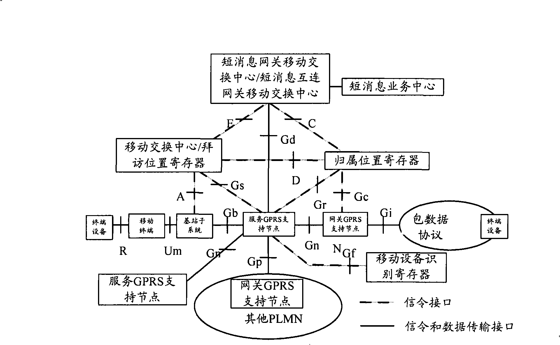
technical field [0001] The present invention relates to the communication field, and more specifically relates to a system for realizing the subnet-dependent aggregation protocol. Background technique [0002] General Packet Radio Service (GPRS for short) superimposes a layer of network on the basis of the original circuit-switching-based Global System for Mobile Communication (GSM for short) to form a GSM / GPRS network, adding Serving GPRS Support Node (Serving GPRSSupport Node, referred to as SGSN), Gateway GPRS Support Node (Gateway GPRSSupport Node, referred to as GGSN), and Packet Control Unit (Packet Control Unit, referred to as PCU) and other entities, and realize multiple networks through the GPRS backbone network The direct connection of entities realizes packet data transmission and improves the data transmission capability of the GSM system. [0003] The network structure of GPRS system is as follows: figure 1 shown. A mobile station (MS) that needs to use GPRS ...

Claims


Application Information

Patent Timeline
Patent Type & Authority Applications(China)
IPC IPC(8): H04L29/08H04L29/06H04L12/56H04Q7/22H04L12/70
Inventor 孙以雷
Owner ZTE CORP
Learn More