
Differential confocal Raman spectra test method

A spectral testing and differential confocal technology, applied in the field of high spatial resolution spectral testing and imaging, can solve the problem of limiting the micro-region spectral detection capability of confocal Raman spectroscopy instruments, the inability to guarantee the excitation spot position of the confocal Raman spectroscopy system, Confocal Raman spectroscopy testing technology cannot be used for micro-area spectral characteristics testing and analysis occasions, etc., to achieve the effect of improving micro-area spectral detection capabilities, improving micro-area spectral detection capabilities, and micro-area geometric scale detection capabilities.

Inactive Publication Date: 2010-07-28
BEIJING INSTITUTE OF TECHNOLOGYGY
View PDF0 Cites 4 Cited by
  • Summary
  • Abstract
  • Description
  • Claims
  • Application Information

AI Technical Summary

Problems solved by technology

[0005] The position of the excitation spot of the confocal Raman spectroscopy system cannot be guaranteed to be at the focal point of the objective lens, and the actual excitation spot is much larger than the focus spot of the objective lens. As a result, the miniaturization of the detectable area is restricted, and the micro The ability to detect the spectrum of the region makes the confocal Raman spectroscopy test technology unable to be used in the occasions of finer micro-region spectral characteristic testing and analysis

Method used


Image

  • Differential confocal Raman spectra test method
  • Differential confocal Raman spectra test method
  • Differential confocal Raman spectra test method

Examples


Embodiment Construction

[0036] The present invention will be further described below in conjunction with drawings and embodiments.

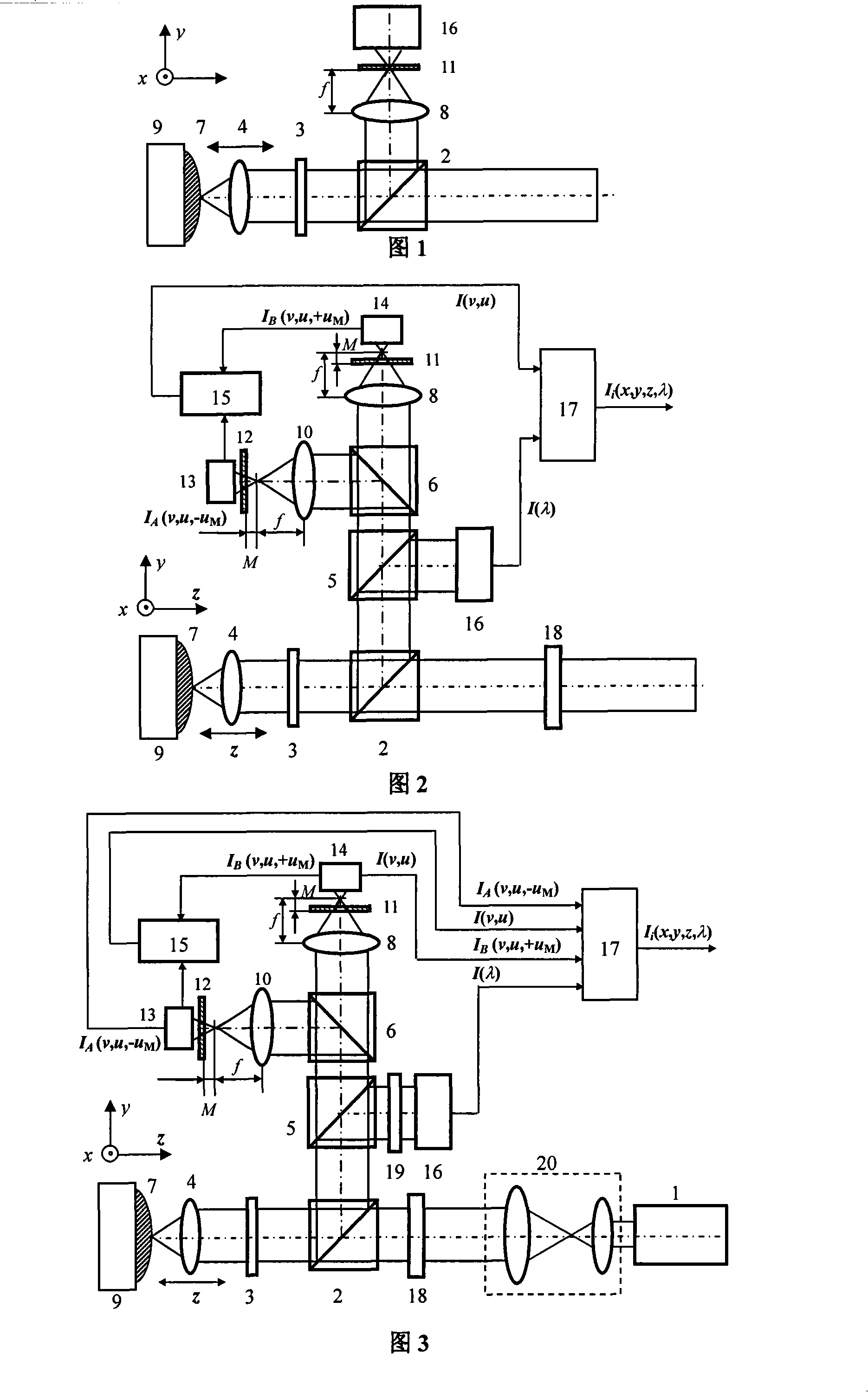
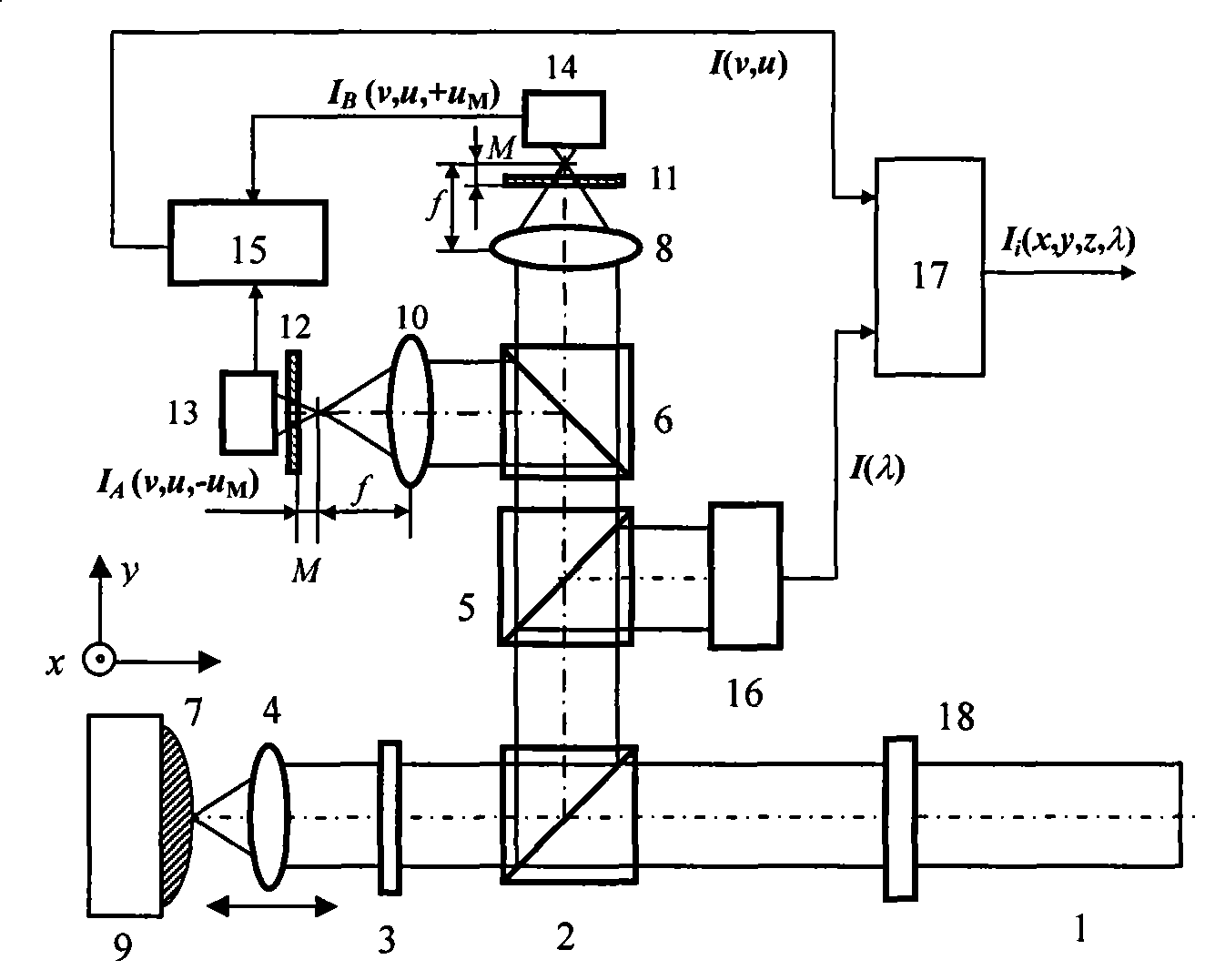
[0037] Such as image 3 As shown, the beam expanded by the beam expander 20 emitted by the laser 1 passes through the pupil filter 18 (amplitude pupil filter) and passes through the polarization beam splitter 2, and then becomes p light whose polarization direction is parallel to the paper. , the p light is focused on the sample 7 by the objective lens 4 after passing through the 1 / 4 wave plate 3, and excites the Raman scattered light of the sample. Part of the laser beam passes back through the 1 / 4 wave plate 3 and turns into s-light whose polarization direction is perpendicular to the paper surface. The polarization beam splitter 2 reflects the s-light to the beam splitter 5. The Raman scattered light is also transmitted by the polarization beam splitter together with the laser beam. 2 reflection reaches the beam splitter 5.

[0038] The beam splitter 5 first divides...


PUM


Abstract

The invention belongs to the micro-spectrum imaging technical field and relates to a differential confocal raman spectral test method. The method integrates the technical characteristics of the differential confocal detection method and the raman spectral detection method, forms a test method capable of realizing sample microarea spectral detection, precisely catches focus positions of excitationlight beams through the differential confocal technology, detects raman spectra of corresponding positions, simultaneously adopts a designed pupil filter, sharpens Airy disc major lobes of a differential confocal raman spectral system, improves the microarea raman spectral detectability and precisely acquires microarea space spectrum information which comprises spectral information and position information of microarea samples. The method obviously improves the microarea spectral detectability of a confocal raman spectromicroscope, has absolute tracking zero points and bipolar tracking characteristics, realizes absolute measurement of physical dimension, can be widely applied in the technical fields such as biomedicine, life sciences, biophysics, biochemistry, industrial precision detection and so on to perform high-precision detection of geometric positions and spectral characteristics of microareas, and has very important application prospect.

Description

technical field [0001] The invention belongs to the technical field of micro-spectral imaging, and relates to a high-spatial-resolution spectral test imaging method of "combining maps and spectra into one", which can be used for micro-region spectral resolution tests of various samples and the like. Background technique [0002] Laser confocal Raman spectroscopy technology causes molecules (or lattices) to vibrate and lose (or gain) part of the energy through incident laser light, so that the frequency of scattered light changes, and the composition and structure of molecules can be detected by analyzing the scattered light And relative content, etc., laser confocal Raman spectroscopy technology is also called molecular probe technology. [0003] Laser confocal Raman spectroscopy testing technology, as an extremely important basic technical method for the measurement and analysis of material structure, is widely used in physics, chemistry, biomedicine, material science, envi...

Claims


Application Information

Patent Timeline
Patent Type & Authority Patents(China)
IPC IPC(8): G01N21/65
Inventor 赵维谦邱丽荣郭俊杰周桃庚
Owner BEIJING INSTITUTE OF TECHNOLOGYGY
Learn More