Method and device for testing rear spectroscopic pupil laser confocal Raman spectrum

A spectral measurement and Raman spectroscopy technology, applied in the field of microscopic spectral imaging, can solve the problems affecting the spatial resolution of confocal Raman spectroscopy systems, difficulty in installation and adjustment, etc. force, the effect of simplifying the structure of the optical path

Inactive Publication Date: 2019-01-15
BEIJING INSTITUTE OF TECHNOLOGYGY
View PDF6 Cites 2 Cited by
  • Summary
  • Abstract
  • Description
  • Claims
  • Application Information

AI Technical Summary

Problems solved by technology

However, due to the failure of this test method to make full use of the effective numerical aperture of the measurement objective lens, the spatial resolution of the confocal Raman spectroscopy system is affected; in addition, the test system is limited by factors such as strict requirements for off-axis positions and difficult installation and adjustment.

Method used


Image

  • Method and device for testing rear spectroscopic pupil laser confocal Raman spectrum
  • Method and device for testing rear spectroscopic pupil laser confocal Raman spectrum
  • Method and device for testing rear spectroscopic pupil laser confocal Raman spectrum

Examples


Embodiment 1

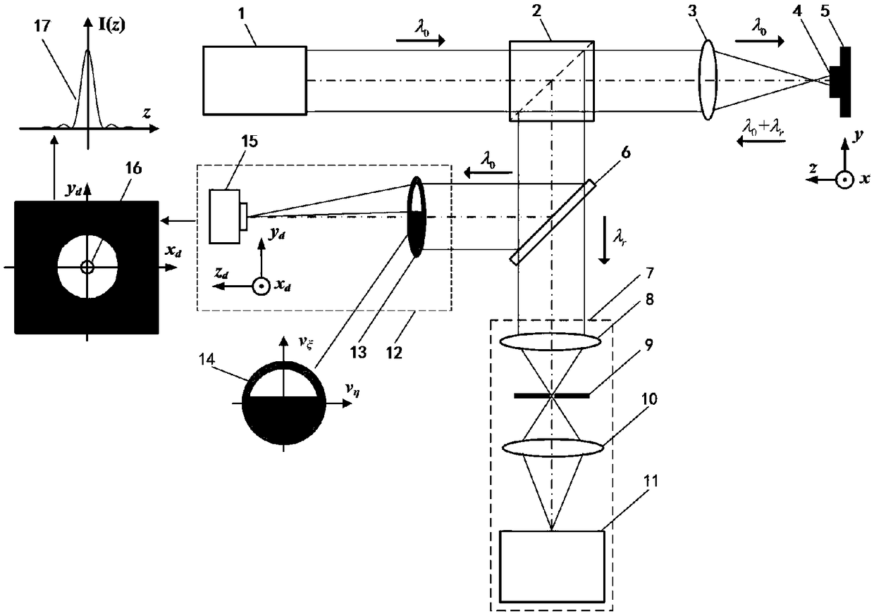
[0056] In this embodiment, the light source system 1 uses a 532nm continuous laser, the dichroic spectroscopic system 6 uses a NotchFilter, and the spectral detection unit 11 uses a Raman spectrometer.

[0057] Such as Figure 11 As shown, the split-pupil laser confocal Raman spectroscopy detection process is as follows:

[0058] First, the laser light emitted from the light source system 1 composed of lasers is converged by the third converging lens 21 into the second pinhole 22, and then collimated and expanded by the fourth converging lens 23 to form a parallel excitation beam. After the excitation beam passes through the radial polarization conversion system 18, the dichroic prism 2 and the pupil filter 19, the measured objective lens 3 converges on the measured sample 4, and excites the Raman scattered light carrying the micro-area characteristic parameters of the measured sample 4 .

[0059] Then the three-dimensional scanning system 5 is controlled by the computer 29 ...


PUM


Abstract

The invention relates to a method and device for testing a rear spectroscopic pupil laser confocal Raman spectrum, and belongs to the technical field of microscopic spectrum imaging. According to themethod for testing the rear spectroscopic pupil laser confocal Raman spectrum, a spectroscopic pupil confocal microscopic imaging system is constructed by Rayleigh scattering light abandoned in a confocal Raman spectrum detection system to realize high spatial resolution detection of the geometrical morphology of a sample; and a focal position obtained by the spectroscopic pupil confocal microscopic imaging system is utilized to accurately obtain Raman spectrum information at the focal point of the sample, so that high spatial resolution imaging and detection of the spectroscopic pupil confocal Raman spectrum of spectrum integration are realized. The method and device for testing the rear spectroscopic pupil laser confocal Raman spectrum have the advantages of accurate positioning, high spatial resolution, high spectrum detection sensitivity and the like, and can be widely applied to the fields of biomedicine, physical chemistry, precision measurement, femtosecond laser processing andthe like.

Description

technical field [0001] The invention relates to a laser confocal Raman spectrum testing method and device with rear split pupils, and belongs to the technical field of microspectral imaging. Combining split-pupil laser confocal microscopy technology with Raman spectroscopy detection technology, it involves a "map-in-one" split-pupil laser confocal Raman spectroscopy testing method and device, which is used to conduct high-level micro-region Raman spectroscopy of samples. Spatially resolved measurements, etc. Background technique [0002] Laser confocal Raman spectroscopy technology changes the frequency shift of the scattered light through the energy exchange between the incident laser and optical phonons, and realizes the non-contact measurement of the composition, concentration, stress, strain, temperature and other parameters of the sample micro-area. Measurement, laser confocal Raman spectroscopy technology is also known as molecular probe technology. This technology h...

Claims


Application Information

Patent Timeline
Patent Type & Authority Applications(China)
IPC IPC(8): G01N21/65G01N21/01
Inventor 邱丽荣吴寒旭赵维谦王允
Owner BEIJING INSTITUTE OF TECHNOLOGYGY
Why Eureka
Try Eureka