Laser differential correlation confocal Raman spectrum test method and device

A spectral measurement, differential confocal technology, applied in measurement devices, Raman scattering, scattering characteristic measurement, etc., can solve the problem that the theoretical spectral spatial resolution has not been improved, to improve the micro-area spectral detection capability, improve the spatial resolution, etc. The effect of resolution

Pending Publication Date: 2021-12-31
BEIJING INSTITUTE OF TECHNOLOGYGY
View PDF1 Cites 0 Cited by
  • Summary
  • Abstract
  • Description
  • Claims
  • Application Information

AI Technical Summary

Problems solved by technology

However, this test method does not change the point spread function of the confocal Raman spectroscopy detection system in principle, so its theoretical spectral spatial resolution has not been improved.

Method used


Image

  • Laser differential correlation confocal Raman spectrum test method and device
  • Laser differential correlation confocal Raman spectrum test method and device
  • Laser differential correlation confocal Raman spectrum test method and device

Examples


Embodiment 1

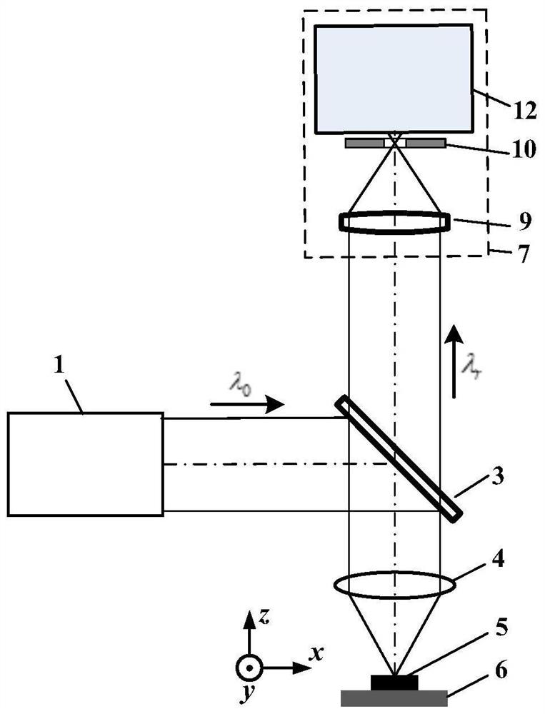
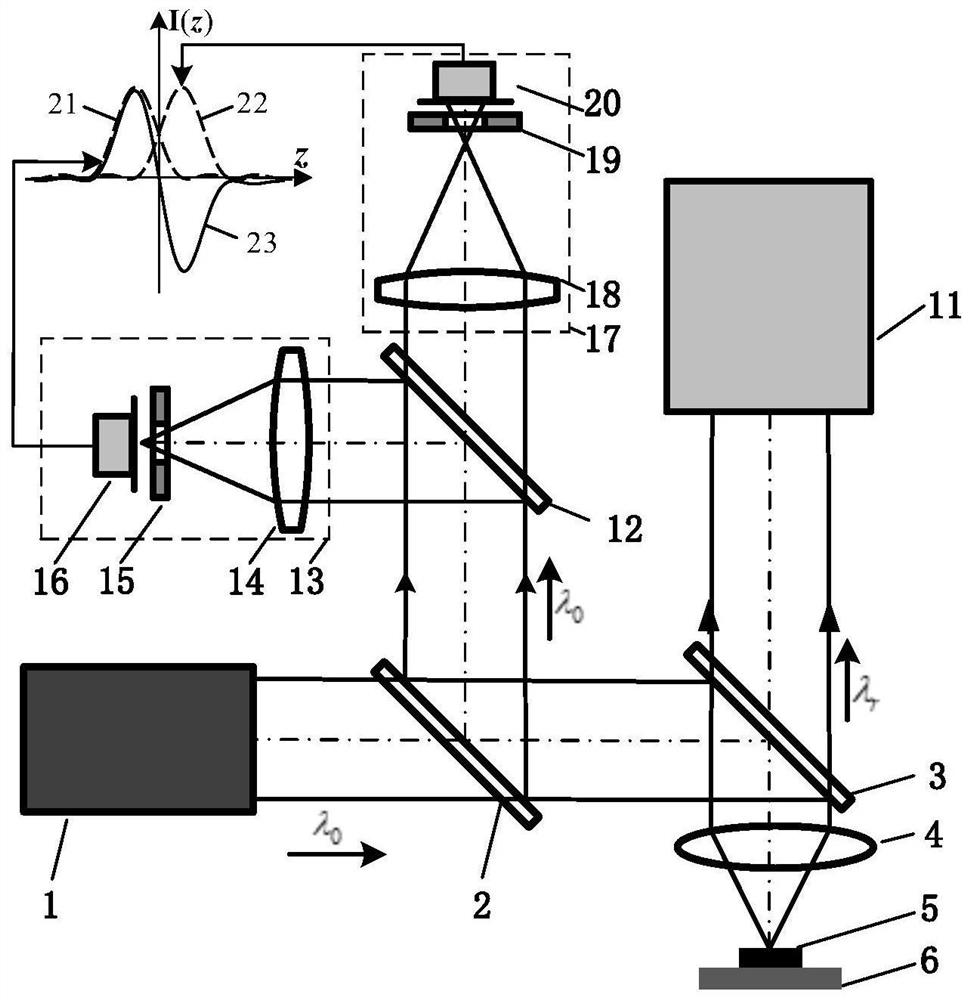
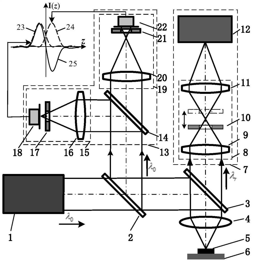
[0052] like image 3 As shown, the laser differential correlation of the laser differential correlation of the present embodiment, the excitation beam emitted by the light source system 1 passes through the first splitter 2 and the filter 3, and the measuring objective mirror 4 will be concentrated to the sample 5 On the upper, Raman scattering light and reflected light carrying the sample micro-zone characteristic parameter information is excited. Raman scattered light, the reflected light is collected by the measuring objective mirror 4, and the filter 3 is divided into two beams, one of which reflects the reflected light reflected by the filter 3 to the differential confocal detection system 13, and the other beam passes through the filter The light sheet 3 enters the associated coke lamser spectrum collection system 7.

[0053] The scattering light and reflected light of the differential confocal detection system 13 are reached, and the second speculatory mirror 14 is divided i...

Embodiment 2

[0060] In the present embodiment, the light source system 1 employs a 532 nm continuous laser, and the filter 3 is NOTCH FILTER, the spectral detector 12 uses a Raman spectrometer.

[0061] like Figure 8 As shown, the laser differential correlation of the coke lam spectrum test method is:

[0062] First, the laser light generated by the light source system 1 of the laser passes through the fifth consecutive girlfriend 29, after the spatial light filter needle 30 is gadped, and the second consecutive girlfriend 31 is returned to form a parallel excitation beam. After the radial polarization conversion system 26, the first score mirror 2, and the pupil filter 27, the NOT FILTER3 is reflected by the Notch Filter3 into the measuring objective mirror 4, and will be gathered on the sample 5, and the sampled sample 5 is stimulated. Raman scattering light, reflected light.

[0063] Then, the three-dimensional scanning system 6 is then controlled by the computer 36 to move the sampled samp...


PUM


Abstract

The invention discloses a laser differential correlation confocal Raman spectrum test method and device, and belongs to the technical field of micro-spectrum imaging. The differential confocal microscopic imaging system is constructed by using reflected light, so that high-precision tracking of a sample focus and high-spatial-resolution detection of geometric morphology are realized; raman scattering light is used for constructing a confocal Raman spectrum imaging system, two Raman spectrum signals at equivalent defocusing positions before and after a focus of a Raman collection lens are obtained by moving a Raman pinhole in the measurement process, and related product processing is performed on the two Raman signals to obtain related Raman spectrum information of a measured position; a confocal Raman system point spread functionis compressed to realize high spatial resolution Raman spectrum imaging; and the two points are combined to realize image-image-in-one imaging with high spatial resolution. The method and device have the advantages of real-time focus high-precision tracking, high spatial resolution, high signal-to-noise ratio and the like, and can be widely applied to the fields of biomedicine, physical chemistry, material science and the like.

Description

Technical field [0001] The present invention relates to a laser differential associated condoviteratum spectral testing method and apparatus, belonging to the field of microscopic spectrum imaging. Background technique [0002] Laser Co-covalrabismation techniques change the energy exchange between the incident laser and the optical phonon, the frequency of the scattering light changes, realizes non-contact measurement of parameters such as the composition of the sample micro zone, concentration, stress, strain, temperature and other parameters. Laser Co-covalrabismation technology is also known as molecular probe technology. The technique has a high space resolution of the confocal micro technology. By chromatographic scans of the sampled samples, the Raman spectrum information of different depths of the sample is obtained, and thereby performing high spatial distinguishing measurement of the sample micro zone in a non-contact manner. . Laser Co-covalrabism Technologies As a tec...

Claims


Application Information

Patent Timeline
Patent Type & Authority Applications(China)
IPC IPC(8): G01N21/65G01N21/47
CPCG01N21/65G01N21/4738G01N21/474
Inventor 赵维谦李荣吉邱丽荣王允
Owner BEIJING INSTITUTE OF TECHNOLOGYGY
Why Eureka
Try Eureka