Novel method and device for measuring ultra-short optical pulse spectrum phase

A technology of ultra-short light and a new method, which is applied in the direction of measuring devices, measuring optics, optical radiation measurement, etc., can solve problems such as the inability to determine polarity, and achieve the effects of improving measurement accuracy and accuracy, improving measurement accuracy, and being easy to use

Inactive Publication Date: 2008-10-29
SUN YAT SEN UNIV
View PDF0 Cites 24 Cited by
  • Summary
  • Abstract
  • Description
  • Claims
  • Application Information

AI Technical Summary

Problems solved by technology

The introduction of this additional phase difference enables the determination of polarity, but it also introduces many disadvantages such as dense interference fringes; in the CDFF-SPIDER

Method used


Image

  • Novel method and device for measuring ultra-short optical pulse spectrum phase
  • Novel method and device for measuring ultra-short optical pulse spectrum phase
  • Novel method and device for measuring ultra-short optical pulse spectrum phase

Examples


Embodiment 1

[0041] Above-mentioned effect of the present invention is realized by following measuring scheme and device:

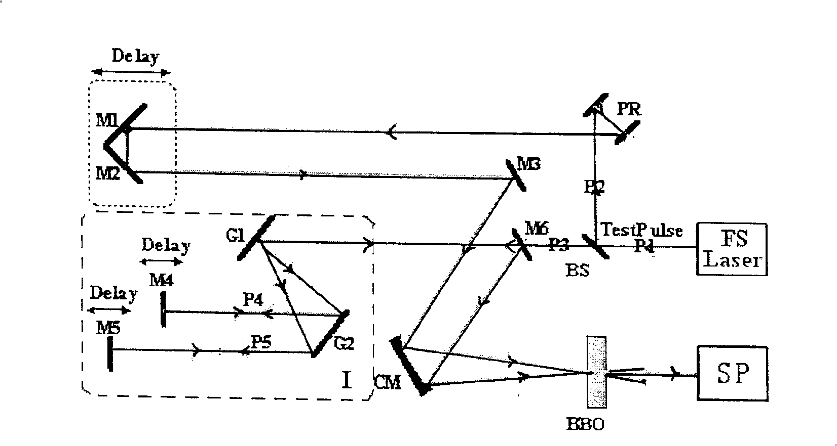
[0042] attached figure 1 Schematic diagram of the measurement device for the FF-SPIDER method. The pulse P1 to be measured generated by the femtosecond laser is divided into reflected light and transmitted light by the beam splitter BS, and the reflected pulse P2 to be measured passes through the periscope PR, mirrors M1, M2, M3 and concave mirror CM to enter the sum frequency crystal , where M1 and M2 form a roof-shaped reflector, and its optical path delay is precisely controlled by a computer; the transmitted pulse P3 through the beam splitter is stretched by a pulse stretcher composed of a grating pair G1 and G2 (1200 lines / mm) The frequency is ω by mirrors M4 and M5 with precise optical delay 0 (ω 0 is the center frequency of the pulse to be measured) and the frequency of the high-frequency quasi-monochromatic light P4 is (ω 0 -Ω) low-frequency quasi-monochr...

Embodiment 2

[0045] Above-mentioned effect of the present invention is realized by following measuring scheme and device:

[0046] attached Figure 5 Schematic diagram of the measurement device for the FF-SPIDER method. The pulse P1 to be measured generated by the femtosecond laser is divided into reflected light and transmitted light by the beam splitter BS, and the reflected pulse P2 to be measured passes through the periscope PR, mirrors M1, M2, M3 and concave mirror CM to enter the sum frequency crystal , where M1 and M2 form a roof-shaped reflector, and its optical path delay is precisely controlled by a computer; the transmitted pulse P3 through the beam splitter passes through a glass column with a length of several centimeters and high dispersion as a stretcher to widen the pulse to be measured. Then it is divided into two equivalent beams of light in space by a dichroic prism, and then the combined mirrors M4 and M5 with time delay function are used to reflect the two beams of li...


PUM


Abstract

The invention relates to a new method for measuring an ultrashort light pulse spectral phase in the field of information optoelectronics and a device thereof. According to the method, a time delay minus T with polarity is introduced between two quasi-monochromatic light components with frequency Omega generated by the chirped stretching of a pulse to be detected; an additional time delay plus T, which is introduced between two quasi-monochromatic light components due to a pulse stretcher, is compensated to be in synchronization with the pulse to be measured and generate two sum frequency lights together with the pulse through a sum frequency crystal; respective power spectra and coherent spectra without interference fringe are acquired through a spectrometer. The phase difference between the two sum frequency lights is calculated by the three spectra through formulae. A spectrum phase curve of the pulse to be measured is calculated by adopting a concatenated method. The method can accurately determine the phase difference polarity of the pulse spectrum, and provide the simple, real-time, rapid and accurate measurement method and the device thereof for measuring the ultrashort optical pulse spectral phase.

Description

technical field [0001] The present invention is a new method for ultrashort light pulse spectral phase measurement applied in the field of information optoelectronics, that is, a Fringe-Free SPIDER method, referred to as FF-SPIDER method and its device. Background technique [0002] The generation and application of ultrashort pulses in the field of ultrafast information optics requires accurate measurement of the envelope and phase structure of optical pulses. attached Figure 4 Shown is the Gaussian envelope of the ultrashort optical pulse electric field and the schematic diagram of the center frequency carrier. A very short optical pulse in the time domain is composed of many carriers with different frequencies, Δγ (frequency width) × Δt (pulse width) = 0.441 (Gaussian pulse). As shown in the figure, the oscillation peak of the frequency carrier overlaps with the envelope peak, that is to say, the initial phase (also known as the absolute phase) of the carrier is zero. ...

Claims


Application Information

Patent Timeline
IPC IPC(8): G01J11/00G01J9/00
CPCG01J11/00
Inventor 雷亮林位株焦中兴赖天树
Owner SUN YAT SEN UNIV
Why Eureka
Try Eureka