10KV electric network terminal disconnection control system

A control system, 10KV technology, applied in the direction of electrical program control, program control in sequence/logic controller, electrical components, etc., can solve the problem of undiscovered 10KV grid terminal disconnection control system, economic loss of power enterprises, power consumption, etc. problems, to achieve the effect of simple structure, reduced power waste, and convenient maintenance

Inactive Publication Date: 2008-10-29
李海芹
0 Cites 0 Cited by

AI-Extracted Technical Summary

Problems solved by technology

However, there are tens of thousands of seasonal or temporary user terminals in the 10KV high-voltage end mentioned above. If the management is not good, the distribution transformer connected to the high-voltage end will be in the state of no-load operation for a long time, and a large amount of electric energy...

Abstract

The invention pertains to the technical field of power network control, in particular to a control system for the disconnection of a 10kV power network terminal. The technical proposal of the control system for the disconnection of the 10kV power network terminal comprises the 10kV power network terminal, a distribution transformer, a falling safety brake connected between the 10kV power network terminal and the distribution transformer, a low-voltage line for the output of the distribution transformer, a line connected with load and a switch mechanism connected between the low-voltage line and the line connected with the load; the upper end of the falling safety brake is provided with a spring sheet and a tripping mechanism which are matched with the end part of a brake tube; the tripping mechanism is connected with the end part of a leverage provided with a fulcrum; the other end of the leverage is controlled by an alternating current contactor; a control mechanism is arranged between the alternating current contactor and the low-voltage line for the output of the distribution transformer. The system can solve the problem that thousands of seasonal or temporary client ends are likely to cause a distribution transformer connected under a high-voltage end to be in the state of no-load operation for a long time; the system also has the advantages of simple line control and convenient maintenance.

Application Domain

Programme control in sequence/logic controllersAc network circuit arrangements

Technology Topic

ContactorEngineering +7

Image

  • 10KV electric network terminal disconnection control system
  • 10KV electric network terminal disconnection control system

Examples

  • Experimental program(1)

Example Embodiment

[0015] The structure and circuit principle of the 10KV grid disconnection control system provided by the present invention will be described in further detail below in conjunction with the accompanying drawings.
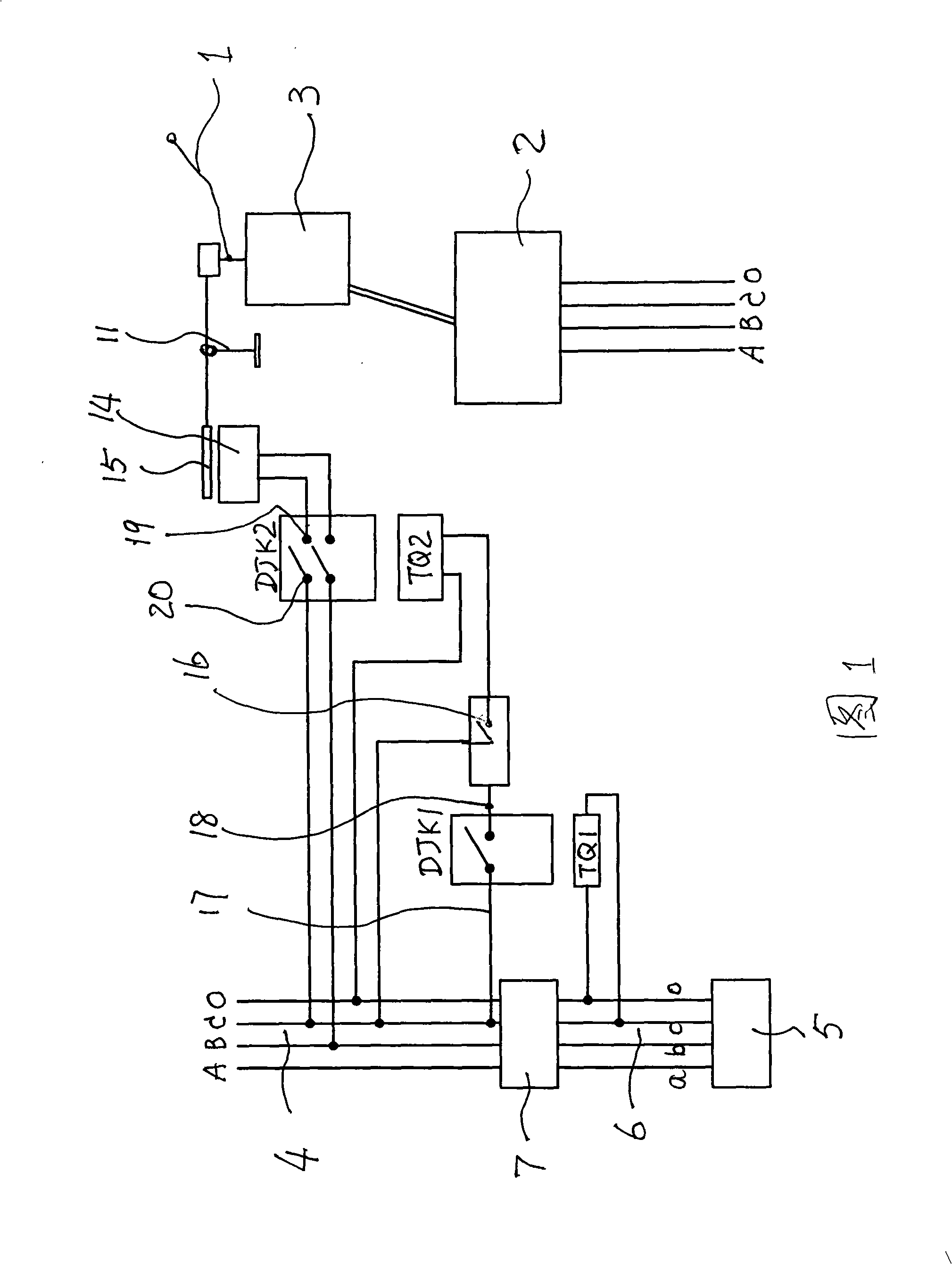
[0016] As shown in Fig. 1, it is the circuit wiring diagram and structural schematic diagram of the 10KV grid disconnection control system provided by the present invention. The 10KV power grid disconnection control system includes: 10KV power grid terminal 1, distribution transformer 2 and drop fuse 3 connected between the two, low-voltage line 4 output by the distribution transformer, line 6 connected to load 5, and line 6 connected to the The switch mechanism 7 between the two;
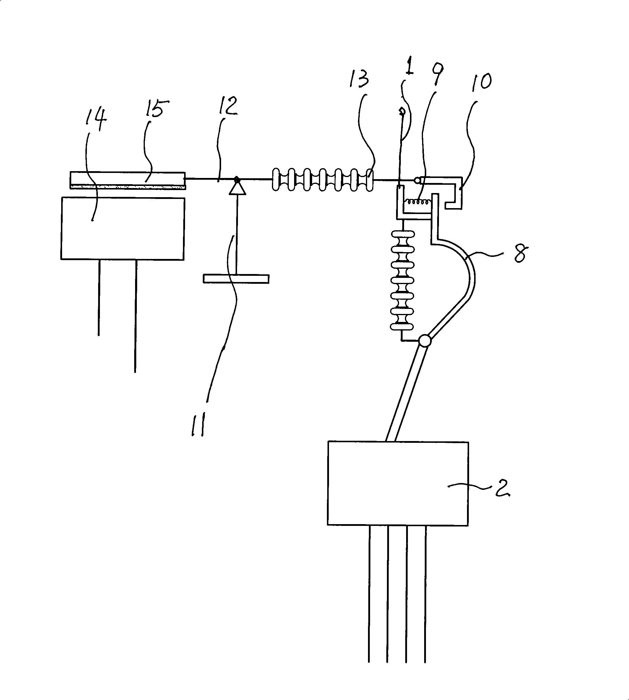
[0017] As shown in Figure 2, the upper end of the above-mentioned fall safety gate is provided with a spring sheet 9 matched with the end of the brake tube 8 and a tripping mechanism 10. The tripping mechanism is connected to a lever 12 provided with a fulcrum 11 by a high-voltage insulated terminal At the control end 13, the other end of the lever mechanism is provided with a pull-in piece 15 controlled by the pull-in coil of the AC contactor 14; it is set between the AC contactor 14 and the low-voltage line output by the distribution transformer There is a control mechanism of the AC contactor composed of a timing control mechanism and a trigger mechanism;
[0018] As shown in Figure 1, the timing control mechanism is composed of a first intermediate relay and a connected timing mechanism. The two ends of the coil TQ1 of the first intermediate relay DJK1 are respectively connected to the live wire c (or a, b) and the neutral wire o connected to the load 5 (or connected to different live wires ab, ac, bc), and to the coil Provide a coil voltage of 220 (or 380) V. The contact 17 on one side of the first intermediate relay is connected to the live wire C (or live wire A, B) of the low-voltage line output by the distribution transformer, and the contact 18 on the other side is connected to the timing switch The input control terminal of 16 is connected; the timing mechanism is constituted by the above-mentioned timing switch 16. The trigger mechanism is composed of a second intermediate relay DJK2. The two ends of the second intermediate relay coil TQ2 are respectively connected to the live line C (or B, A) and the neutral line O of the low-voltage line output by the distribution transformer to provide the coil 220V coil voltage, one end of the wire is connected to the timing switch 16 and controlled by the timing switch; the contacts on both sides of the second intermediate relay DJK2, one of the two contacts 19 on one side is the same as the AC contactor 14 Connected, the two contacts 20 on the other side are connected to the live wire A (or B, C) and the neutral wire O of the low-voltage line output by the distribution transformer to provide a coil voltage of 220V to the coil.
[0019] Its working principle is:
[0020] When the load 5 is working, the coil TQ1 of the first intermediate relay DJK1 has a coil voltage of 220 (or 380) V, so that the first intermediate relay DJK1 is in the off state, and the timer switch 16 is in the off state at the same time , So that the second intermediate relay DJK1 is also in the off state, and the trip mechanism 10 arranged at the control end 13 formed by the high-voltage insulated terminal of the lever 12 buckles the upper end of the drop safety gate to make it in a working and energized state.
[0021] When the switch 7 of the load 5 is turned off and stops working, the voltage at both ends of the coil TQ1 of the first intermediate relay DJK1 is 0, so that the first intermediate relay DJK1 is in a closed state. At this time, the timer starts counting, and when the count reaches After the set time, the timer switch 16 is closed and turned on, then the electrical coil TQ2 of the second intermediate relay DJK1 is turned on, and at the same time the two sets of contacts 19 and 20 on both sides of the relay are turned on, so that the AC contactor absorbs the end of the lever The pull-in piece 15 at the other end, the tripping mechanism 10 at the other end is tilted and detached from the brake tube that will drop the safety gate. The fall safety gate is ejected and disconnected under the action of the matching spring sheet 9, so that the 10KV power grid is disconnected. The matching transformer of the terminal apartment is disconnected, achieving the purpose of 10KV power grid disconnection control.

PUM

no PUM

Description & Claims & Application Information

We can also present the details of the Description, Claims and Application information to help users get a comprehensive understanding of the technical details of the patent, such as background art, summary of invention, brief description of drawings, description of embodiments, and other original content. On the other hand, users can also determine the specific scope of protection of the technology through the list of claims; as well as understand the changes in the life cycle of the technology with the presentation of the patent timeline. Login to view more.

Similar technology patents

Device and method for acquiring electrolyte in AGM partition plate by lead-acid storage battery

ActiveCN108649283AImprove extrusion efficiencyreduce energy waste
Owner:TIANNENG GRP HENAN ENERGY TECH

New-idea screen control system

Owner:天津中科融机电工程有限公司

Automatic gas source distributor with safety function

Owner:YANCHENG LIYAN NEW MATERIAL CO LTD

Classification and recommendation of technical efficacy words

Why Eureka
Try Eureka