
Controller for controlling a drive mechanism of a powered industrial truck

A technology of ground transportation and power drive, which is applied in the direction of motor vehicles, trolleys, multi-axis trolleys, etc. It can solve the problems that the connection contacts of the Hall sensor are bent, cannot guarantee reliable functions indefinitely, and jump start.

Active Publication Date: 2008-10-29
REMA LIPPRANDT GMBH & CO KG
View PDF1 Cites 3 Cited by
  • Summary
  • Abstract
  • Description
  • Claims
  • Application Information

AI Technical Summary

Problems solved by technology

[0004] Although it is prevented in this way that in the event of a misadjustment of the Hall sensor, the ground transport vehicle is in motion despite the neutral position of the travel control handle, however, the misalignment leads to a change in the relationship of the Hall voltage to the position of the travel control handle, Thus, for example, ground transport vehicles can start jumping or not at first when the magnetic carrier is displaced from its neutral position and the safety switch does not work, depending on the relationship between the Hall voltage and the position of the travel controller handle due to the imbalance In which direction has the change occurred,
[0005] In addition, when the Hall sensor is severely misaligned, repeated one-sided impacts of the magnet on the surface of the Hall sensor may occur, which leads to repeated bending of the connecting contacts of the Hall sensor.
This condition can lead to fatigue fractures of the connecting contacts after several actuations of the travel controls
This is very dangerous for the operator, because the signal generated by the electronic system corresponds to the theoretical value "full speed forward" or "full speed backward" according to its design, as long as no other safety system is present , causing the vehicle to move suddenly
[0006] In addition, microswitches cannot be guaranteed to function reliably indefinitely due to their mechanical mode of operation, which is subject to wear and tear
It has been found in practice that the triggering of the microswitch becomes more and more sluggish as the number of operating cycles increases, i.e. at a greater deflection angle of the magnetic carrier, which also leads to a jumpy start of the ground transport vehicle

Method used


Image

  • Controller for controlling a drive mechanism of a powered industrial truck
  • Controller for controlling a drive mechanism of a powered industrial truck
  • Controller for controlling a drive mechanism of a powered industrial truck

Examples


Embodiment Construction

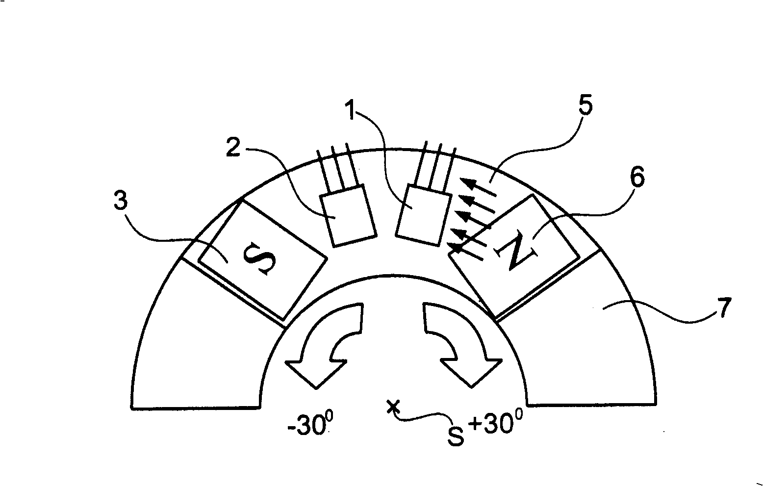
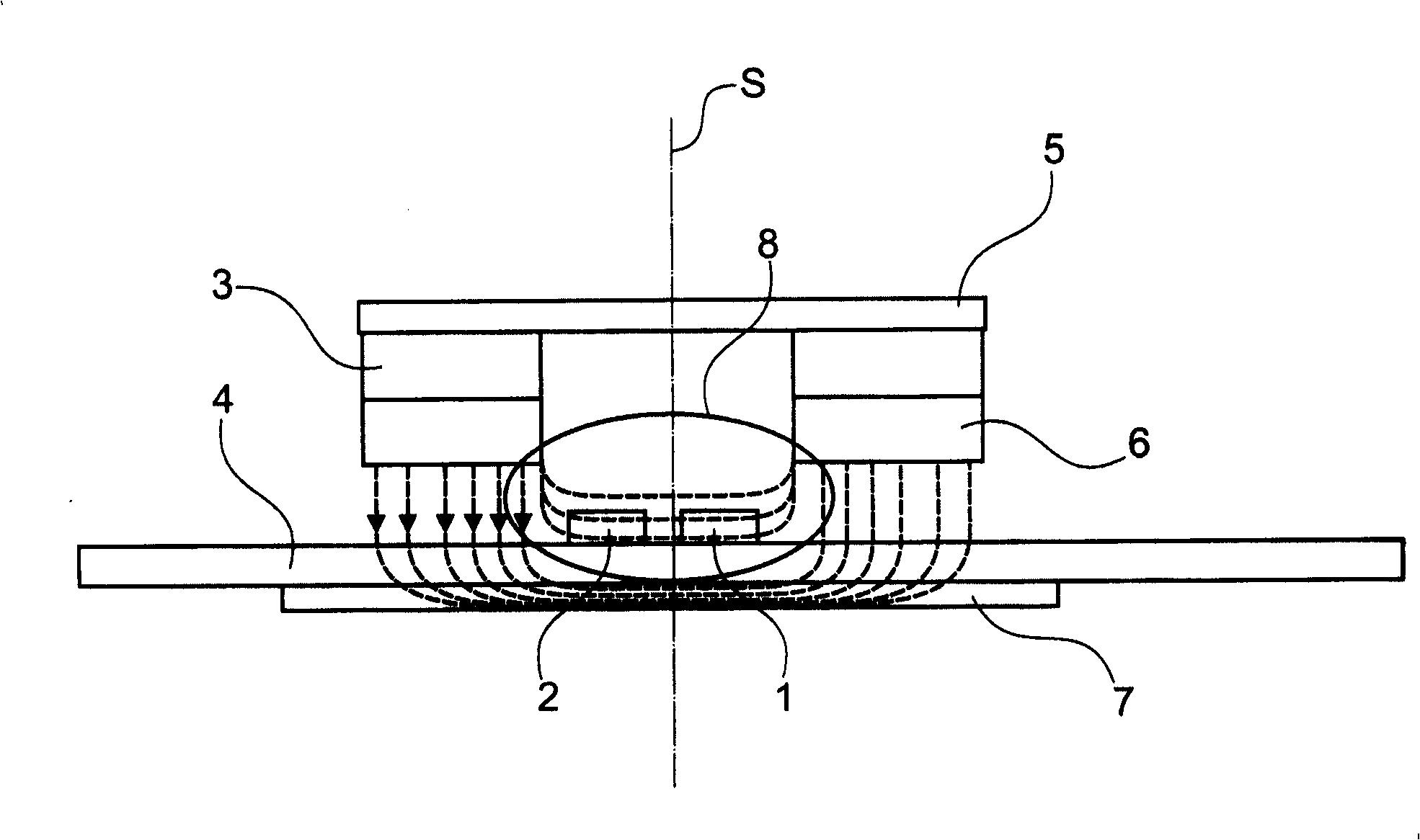
[0024] The illustrated embodiment of the drive controller according to the invention comprises a first Hall sensor 1 and a second Hall sensor 2, which are arranged on a circular arc and fixed flat on a printed circuit board 4 with lateral angular spacing. on one side of the Above the printed circuit board 4 two permanent magnets 3 , 6 are arranged on a yoke 5 . The permanent magnets 3 and 6 are positioned such that their pole axes run parallel but in opposite directions. The yoke 5 serves on the one hand as a magnetic carrier and on the other hand serves to conduct the magnetic flux lines from one permanent magnet to the other in a bundled manner.

[0025] The yoke 5 is partially annular and can be figure 1 and 2 The intermediate positions shown in are offset about the axis S by about ±30°.

[0026] Also arranged on the side of the printed circuit board 4 opposite the Hall sensors 1 , 2 is a magnetic yoke 7 which is likewise of partially annular design and extends over an ...


PUM


Abstract

The controller for controlling the drive mechanism of a powered industrial truck comprises two hall-effect sensors, which are located at a lateral distance from one another, and a source of lines of magnetic flux, which can be displaced relative to the hall-effect sensors when the controller is actuated so that the magnetic flux density changes in the hall-effect sensors.

Description

technical field [0001] The invention relates to a travel controller for controlling the travel gear of a powered ground transportation vehicle. Background technique [0002] A travel controller is known from EP 1 180 473 A1, which comprises a Hall sensor and two permanent magnets on a circular segment-shaped magnetic carrier. The magnetic carrier has a gap between the two permanent magnets, into which the Hall sensor protrudes vertically, so that the magnetic field, which is generated by the permanent magnets facing each other with poles of different polarity, passes through the Hall sensor . The magnetic carrier is connected to the ride control handle actuated by the operator in such a way that it is deflected relative to the Hall sensor during actuation of the ride control handle in such a way that one or the other permanent magnet approaches the Hall sensor so that According to the manipulation and the degree of deflection of the magnetic carrier, the magnetic field pas...

Claims


Application Information

Patent Timeline
Patent Type & Authority Applications(China)
IPC IPC(8): H03K17/97H03K17/95B62B3/06
CPCB62B3/0612H03K17/9502H03K17/97
Inventor K·施坦德克
Owner REMA LIPPRANDT GMBH & CO KG
Learn More