
Robustness tuning fork vibrating type micromechanical gyroscope

A micro-mechanical gyro and vibrating technology, which is applied in the direction of generator/motor, gyro effect for speed measurement, gyroscope/steering sensing equipment, etc., can solve the problems of sensitive processing error, environmental interference, low precision, etc., and achieve greater Effects of stiffness ratio, elimination of interference, and reduction of air damping

Inactive Publication Date: 2011-09-14
TONGJI UNIV
View PDF0 Cites 2 Cited by
  • Summary
  • Abstract
  • Description
  • Claims
  • Application Information

AI Technical Summary

Problems solved by technology

[0003] For micromechanical gyroscopes, no matter whether the drive method is electrostatic drive or electromagnetic drive, the detection method is piezoresistive detection or capacitive detection, or the package is vacuum package or atmospheric pressure package, the goal is to improve the performance of the device. However, Most of the current micro-mechanical gyroscope products have low precision and are sensitive to environmental interference and processing errors. They are mainly used in the low-end and middle-end fields that do not require high precision. In the field, the idea of ​​product robust design is introduced. In the design stage, a reasonable structure is designed so that the performance of the micro-mechanical gyroscope has a strong anti-interference ability against unpredictable changes caused by various environmental factors and processing errors, so that Improving the reliability and stability of micromachined gyroscopes

Method used


Image

  • Robustness tuning fork vibrating type micromechanical gyroscope
  • Robustness tuning fork vibrating type micromechanical gyroscope
  • Robustness tuning fork vibrating type micromechanical gyroscope

Examples


Embodiment Construction

[0025] The robust tuning fork vibrating micromechanical gyroscope of the present invention will be further described below in conjunction with the accompanying drawings.

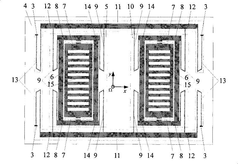
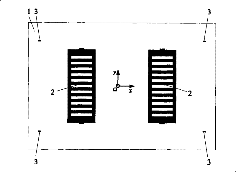
[0026] Such as figure 1 As shown, two sets of grid-shaped fixed electrodes 2 for symmetrical detection are formed on the first substrate 1 , and anchor points 3 on both sides connected to the second substrate 4 are fixed on the first substrate 1 .

[0027] Such as figure 2 As shown, the second substrate 2 suspended above the first substrate 1 is composed of left and right structures and an intermediate structure connecting the left and right structures. The left structure 5 includes a proof mass 6 that can vibrate along the detection direction (y direction), four detection elastic beams 7 between the proof mass and the driving mass, and can vibrate along the driving direction (x direction) perpendicular to the detection direction. A driving mass 8 of vibration, four driving elastic beams 9 connected with ...


PUM


Abstract

A haleness type tuning fork vibration type microcomputer top, includes a first baseplate and two groups of symmetrical bar shape fixing electrodes for measurement, four anchor points fixed on the first baseplate, a second baseplate suspended above the first baseplate. the second baseplate includes a left structure and a right structure and a middle structure connected therebetween, wherein the left structure includes a detection quality block vibrating along the detection direction (the y direction), four detection elastic beams between the detection quality block and the driving quality block, a driving quality block vibrating along the driving direction (the X direction) vertical to the detection direction and four driving elastic beams connected with the driving quality block. The middle structure includes two coupled quality block sconnected with the driving elastic blocks, a middle coupled elastic beams connected with the middle coupled quality block. The top has no need to be packed in the vacuum with higher sensitivity and bandwidth, better capacity of resisting disturbance, which is not sensitive to the environment and the machine error with better haleness.

Description

technical field [0001] The invention belongs to the field of micro-electro-mechanical systems, and relates to a robust tuning fork vibrating micro-mechanical gyroscope, in particular to a tuning-fork vibrating micro-mechanical gyroscope whose left and right structures are indirectly connected, driven and detected by synovial film damping. Background technique [0002] The micromechanical gyroscope is a micro inertial sensor that uses the Coriolis effect to detect the angular velocity of a rotating object. Micromechanical gyroscopes prepared by microelectronic machining technology are widely used in aerospace, military, automotive, and consumer electronics products due to their low cost, small size, light weight, low power consumption, simple structure and process, and suitable for mass production. and other fields. The original micromechanical gyroscope was proposed in 1993, with only one mass block and one elastic beam. With the development of silicon micromachining techn...

Claims


Application Information

Patent Timeline
Patent Type & Authority Patents(China)
IPC IPC(8): G01C19/56B81B7/02B81B3/00G01C19/5621
Inventor 王安麟文永蓬刘广军姜涛
Owner TONGJI UNIV
Learn More