Exhaust particulate filter

A particle filter and filter technology, which is applied in the fields of dispersed particle filtration, dispersed particle separation, chemical instruments and methods, etc., can solve problems such as limiting the selection of filter body materials.

Inactive Publication Date: 2008-11-05
GM GLOBAL TECH OPERATIONS LLC
View PDF0 Cites 4 Cited by
  • Summary
  • Abstract
  • Description
  • Claims
  • Application Information

AI Technical Summary

Problems solved by technology

Arrangements of catalysts or heat within the exhaust system to achieve filter element regeneration tend to generate high temperatures within the filter body, which tends to limit the choice of material for the filter body

Method used


Image

  • Exhaust particulate filter
  • Exhaust particulate filter
  • Exhaust particulate filter

Examples


Embodiment Construction

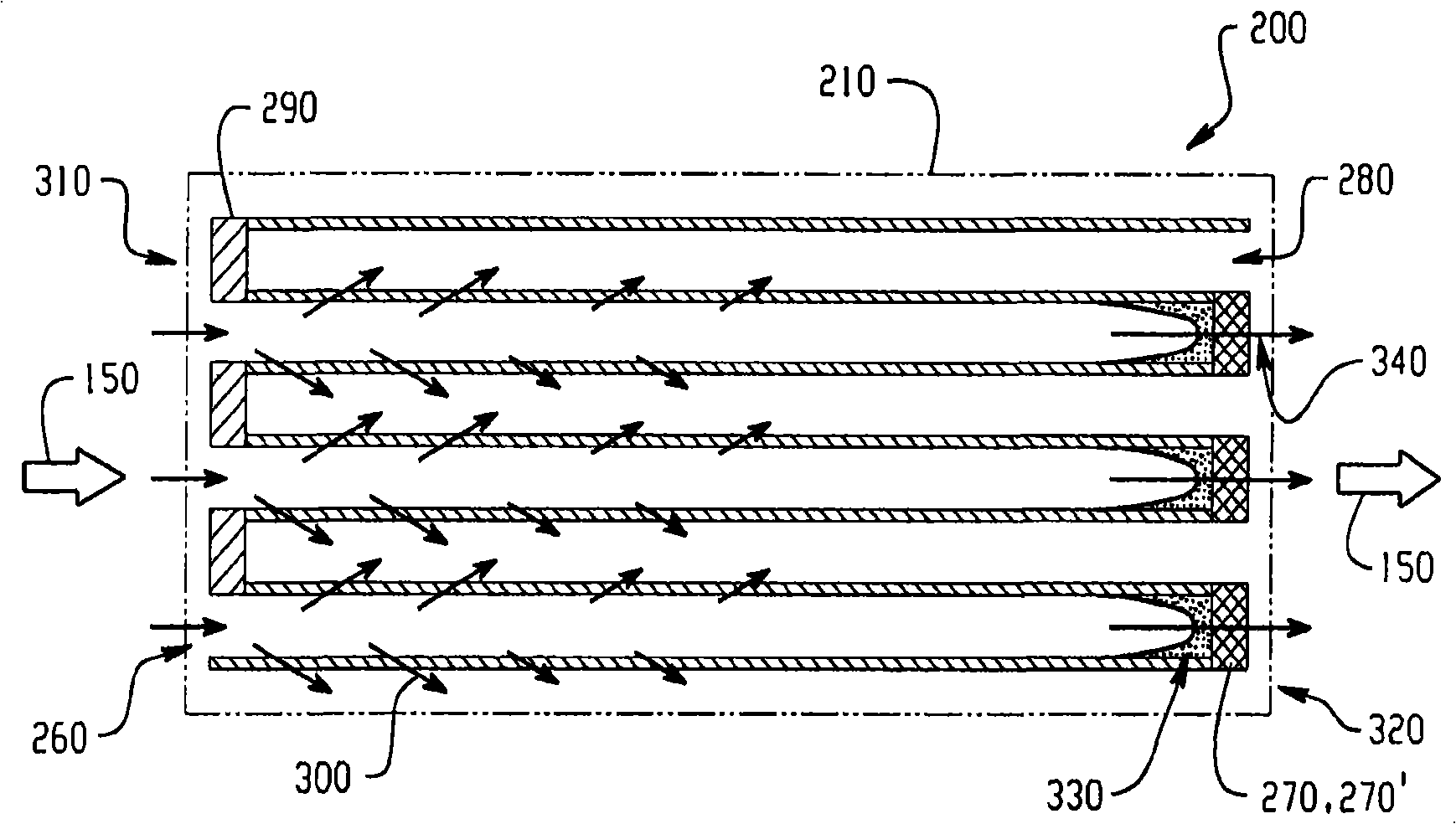
[0011] Embodiments of the present invention provide a particulate filter with improved regeneration characteristics for use in an exhaust system of an automotive diesel engine. While the embodiments described herein represent an automotive diesel engine as an exemplary diesel power plant using a particulate filter, it should be understood that the disclosed invention can also be applied to vehicles requiring the functionality of the particulate filter disclosed herein. Other diesel powered units, such as diesel generators. While the disclosed invention is well suited for filtering the by-products of combustion of diesel engines, it is also applicable to filtering the by-products of combustion of gasoline engines.

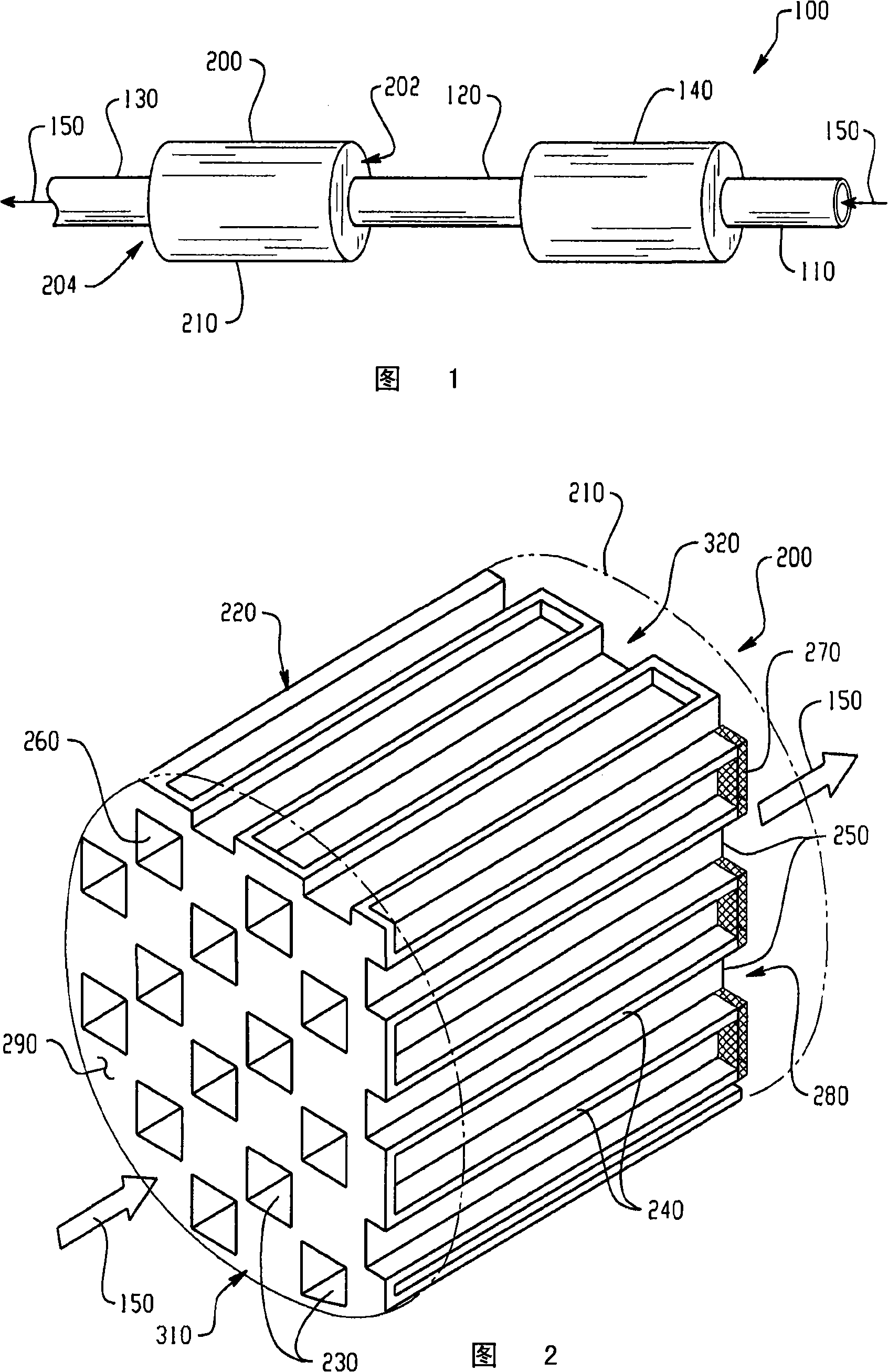
[0012] An exemplary exhaust system 100 for an automotive diesel engine (not shown) is shown in FIG. 1, the exhaust system 100 having a manifold exhaust pipe 110 suitably connected at one end to An exhaust manifold (not shown) of a diesel engine (not shown) to recei...


PUM


Abstract

A particulate filter for an exhaust system configured to receive an exhaust flow is disclosed. The filter includes a wall-flow filtration element having a first regeneration zone and a second regeneration zone, the first zone being downstream of the second zone, and a heat source disposed at the first regeneration zone. In response to demand for regeneration, the wall-filtration element regenerates according to a staged regeneration such that the first zone initiates regeneration ahead of the second zone, and each zone regenerates in the direction of the exhaust flow.

Description

technical field [0001] The present invention relates generally to exhaust systems, and more particularly to particulate filters for diesel engine exhaust systems. Background technique [0002] Automotive exhaust systems for diesel and other internal combustion engines typically include filtration systems that restrict particulate matter from being emitted with the exhaust gases. In diesel engine systems, this material typically includes carbonaceous material (soot) and dust particles. Current filtration methods for capturing exhaust particulate matter focus on wall flow filtration. Wall flow filter systems generally have a high filtration efficiency not only for exhaust particulate matter but also for dust particles. Catalytic diesel particulate filters have been widely used, where a catalyst is usually applied to the front end of the diesel particulate filter or to the entire filter to lower the regeneration temperature. The arrangement of catalysts or heat within the ex...

Claims


Application Information

Patent Timeline
Patent Type & Authority Applications(China)
IPC IPC(8): B01D46/00
Inventor S·-W·S·程
Owner GM GLOBAL TECH OPERATIONS LLC
Why Eureka
Try Eureka