Silicon oil fan clutch

A clutch and fan technology, applied in clutches, fluid clutches, machines/engines, etc., can solve the problems of control accuracy limitation, response time lag, etc., to achieve accurate control, rapid response, and great significance for energy saving and emission reduction.

Inactive Publication Date: 2008-11-12
叶舟
View PDF0 Cites 14 Cited by
  • Summary
  • Abstract
  • Description
  • Claims
  • Application Information

AI Technical Summary

Problems solved by technology

In the traditional silicone oil fan clutch, the deflection of the valve plate is controlled by the heat-sensitive helical bimetallic spring temperature sensor, so the response time has a certain lag and the control accuracy will be limited

Method used


Image

  • Silicon oil fan clutch

Examples


Embodiment Construction

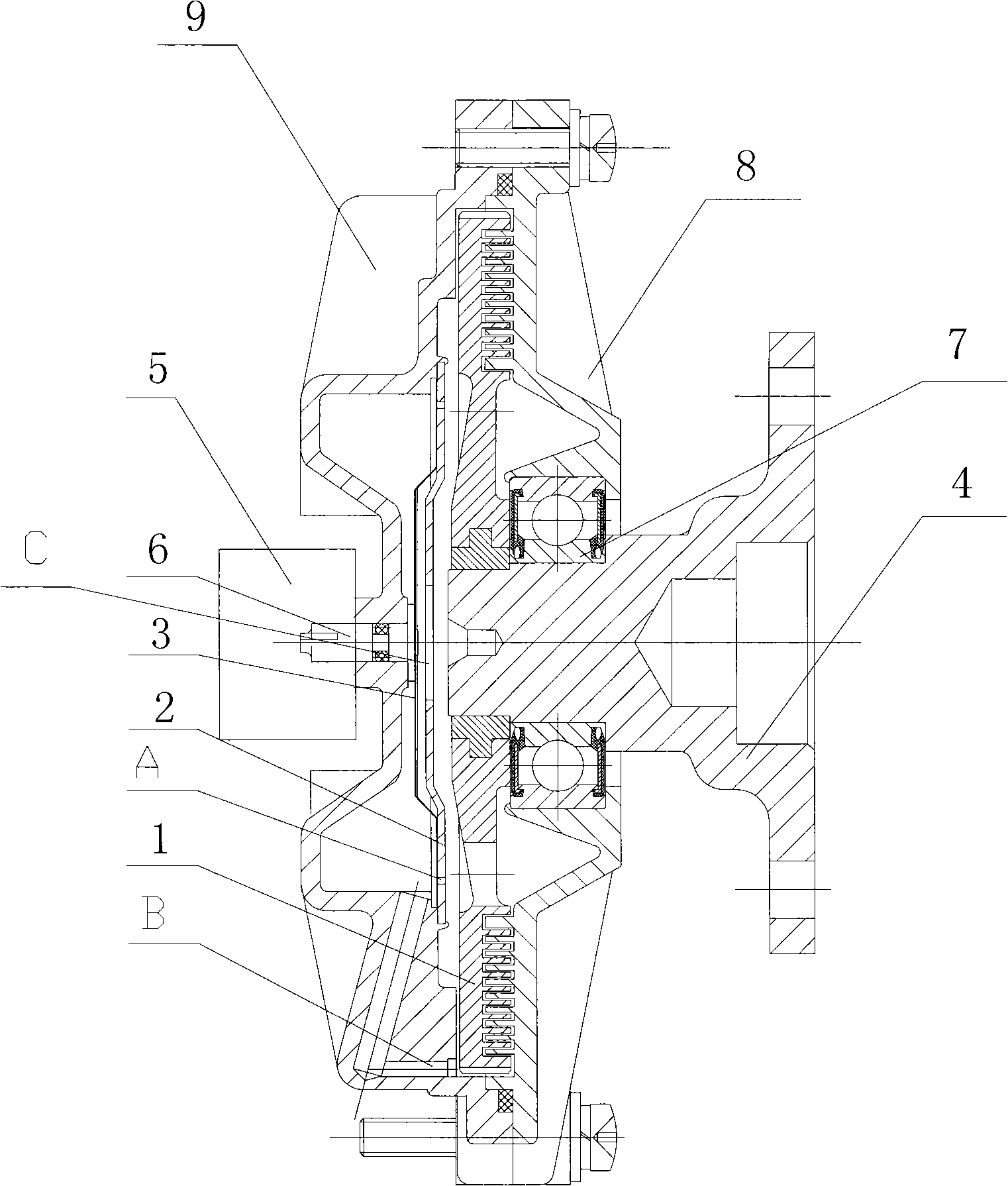
[0012] The accompanying drawings show the structure of the present invention and its embodiments, and the relevant details and working principles of the embodiments will be further described below in conjunction with the accompanying drawings. The silicone oil fan clutch includes a housing 8, a front cover 9, a driving plate 1, a driven plate 2, a valve plate 3, a driving shaft 4, a temperature sensor (not shown in the figure), a valve plate shaft 6, a bearing 7, a fan And other composition. The front end of the valve disc shaft 6 is equipped with a control unit that enables the valve disc 3 to open or close the oil inlet A, the cavity between the driven plate 2 and the front cover 9 is an oil storage tank, and the driven plate 2 The labyrinth cavity between the housing 8 is a working cavity, the active plate 1 is connected with the active shaft 4, and the control unit is composed of an executive component, a temperature sensor and an ECU. The temperature sensor can be a precision...


PUM


Abstract

The invention discloses an improved invention of a silicon oil fan clutch, which is essentially characterized in that a control component is composed of an executing unit, a temperature sensor and an ECU. The executing component and the temperature sensor are respectively connected with the ECU. In the invention, as a previous thermal sensitive spiral and bimetal spring temperature detector is modified into an electronic temperature sensor for detecting the temperature, and then the detected temperature is fed back to the ECU (an electronic controller unit) which rapidly sends out an order to cause the executing unit to be operated after distinguishing treatment, an oil inlet is opened and closed rapidly and precisely by a valve. Compared with the prior art, the invention has outstanding substantive features and obvious progress.

Description

Technical field: [0001] The invention relates to an improved invention for controlling a silicon oil fan clutch mechanism on an automobile cooling system, and specifically relates to an invention for electronically controlling a silicon oil fan clutch. Background technique: [0002] In the prior art, the fan is the consumer of engine power, and the maximum time is about 10% of the engine power. In order to reduce fan power consumption, reduce noise and wear, prevent engine overheating, reduce pollution, and save fuel, fan clutches are often used. In the traditional silicon oil fan clutch, the deflection of the valve plate is controlled by the thermosensitive spiral bimetal spring temperature sensor, so the response time has a certain lag, and the control accuracy will be limited. Summary of the invention: [0003] The technical problem solved by the present invention is to provide a mechanism for controlling the silicon oil fan clutch on an automobile with simple structure and r...

Claims


Application Information

Patent Timeline
Patent Type & Authority Applications(China)
IPC IPC(8): F01P7/12F16D35/00
Inventor 叶舟
Owner 叶舟
Why Eureka
Try Eureka