Ethernet switching system based on cable TV transmission network

A cable television and switching system technology, applied in transmission systems, data exchange details, telephone communications, etc., can solve the problem of high cost, achieve the effects of improving stability and reliability, simple and easy engineering installation, and improving network maintenance capabilities

Inactive Publication Date: 2008-11-19
HANGZHOU SHENGMAO TECH
View PDF1 Cites 7 Cited by
  • Summary
  • Abstract
  • Description
  • Claims
  • Application Information

AI Technical Summary

Problems solved by technology

However, the launch of DOCSIS 3.0 adopts the frequency band channel bonding technology. In general, four channels can be bonded together, and the downlink bandwidth can reach 160M, and the uplink bandwidth can reach up to 120M, which overcomes the shortage of CMTS bandwidth, but so far , there is no DOCSIS3.0 product launched yet, only the quasi-DOCSIS3.0 product is launched, which basically realizes the functions of DOCSIS3.0, but the cost is relatively high

Method used


Image

  • Ethernet switching system based on cable TV transmission network
  • Ethernet switching system based on cable TV transmission network
  • Ethernet switching system based on cable TV transmission network

Examples


Embodiment 1

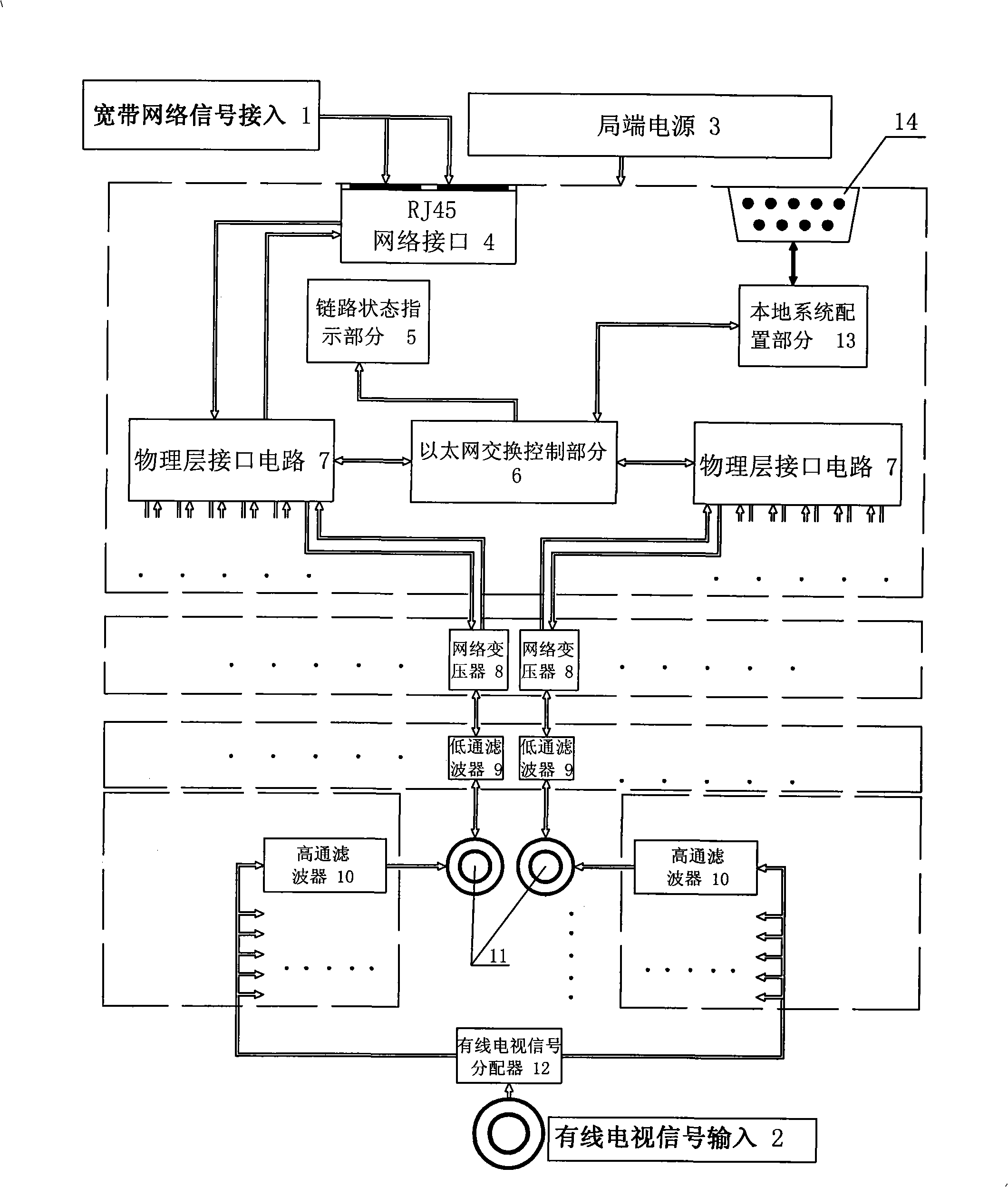
[0032] Embodiment 1, this example is the combination of central office equipment and passive client:

[0033] Such as figure 1 As shown, the central office equipment described in this example consists of a central office power supply 3, an RJ45 network interface 4, a link status indication part 5, an Ethernet switching control part 6, a physical layer interface circuit 7, a network transformer 8, and a low-pass filter 9. Composed of high-pass filter 10, coaxial cable terminal 11, cable TV signal distributor 12, local system configuration part 13 and local control port 14. Among them, one broadband network signal (IP DATA) 1 is connected from the RJ45 network interface 4, and the output terminal of the network interface is connected to the physical layer interface circuit 7, and the physical layer interface circuit 7 is connected to the Ethernet switching control part 6 and the network transformer 8 at the same time. connected, the output end of the network transformer 8 passe...

Embodiment 2

[0042] Embodiment 2, this example is the combination of central office equipment and active client:

[0043] Since the structure of the central office equipment is the same as that of Embodiment 1, this example will not repeat the description, but focuses on the structure of the active client.

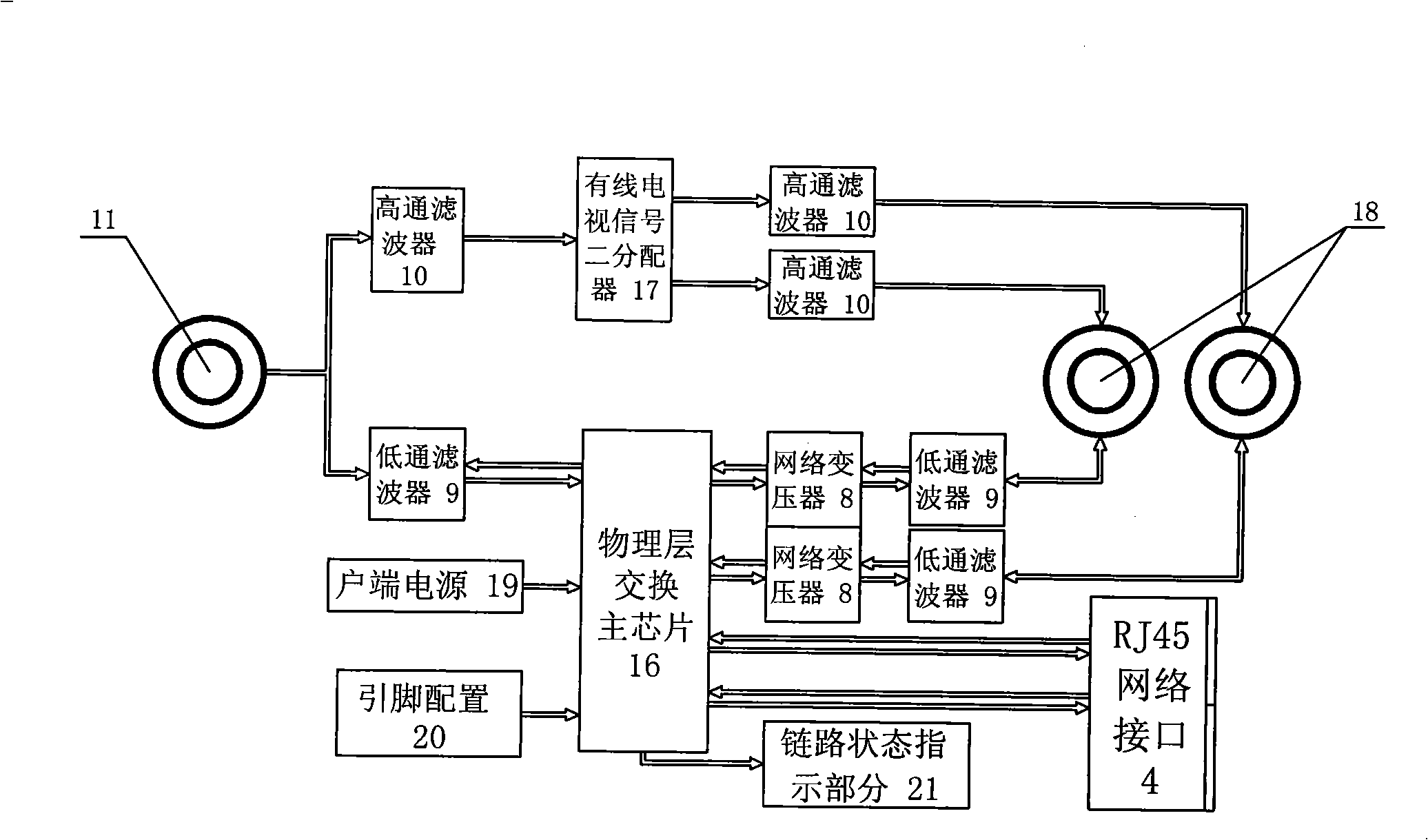
[0044] image 3 The terminal equipment shown is the active client. The low-frequency part of the mixed signal from the coaxial cable terminal 11 is input to the physical layer switching main chip 16 through the low-pass filter 9, and the output signal of the main chip is passed through the network transformer 8 and The low-pass filter 9 is connected to the mixed signal output port 18 of the active terminal. The physical layer switching main chip 16 is also connected to the client power supply 19 , pin configuration 20 , link state indication part 21 and RJ45 network interface 4 . The high-frequency part of the mixed signal from the coaxial cable terminal 11 is output to the mixed sig...


PUM


Abstract

The invention relates to an Ethernet switching system based on the CATV cable transmission network. The technical problem solved by the invention is to provide an Ethernet switching system which has the advantages of the lowest access cost, the simplest engineering reform and stable performance. The technical proposal includes that the Ethernet switching system based on the CATV cable transmission network comprises a local end device and a terminal device, and is characterized in that the local end is composed of a local end power supply, an RJ45 network interface, a link state indication part, an Ethernet switching control part, a physical layer interface circuit, a network transformer, a low pass filter, a high pass filter, a coaxial cable terminal, a CATV signal distributor, a local system configuration part and a local control port; the terminal device comprises a passive client and an active client. The Ethernet switching system based on the CATV cable transmission network is applicable to the last a hundred meters centralized distribution access part in the bidirectional reform of the broadcast television network and realizes the starting of the user broadband service or the video on demand (VOD) television interaction service.

Description

technical field [0001] The present invention relates to the field of digital switching and signal transmission, in particular to an Ethernet switching system based on a cable television line transmission network, that is, the system in the switching field adopts a relatively mature Ethernet switching system at present, and breaks through the traditional The Ethernet adopts the thinking mode of 5 kinds of unshielded twisted pair or optical fiber transmission medium, and proposes to use the cable TV cable (coaxial cable) medium to transmit Ethernet (broadband) data without affecting the existing cable TV business. transmission. [0002] The present invention is suitable for the last 100 meters centralized distribution and access part in the two-way transformation of the radio and television network, to realize the opening of user broadband services or video-on-demand (VOD) TV interactive services, and is also very suitable for simple engineering transformation of guest rooms in ...

Claims


Application Information

Patent Timeline
Patent Type & Authority Applications(China)
IPC IPC(8): H04L12/02H04M11/06H04L29/02
Inventor 周秀菊陶琦徐旭日朱晓华
Owner HANGZHOU SHENGMAO TECH
Why Eureka
Try Eureka