
Non-coherent frequency compensation, demodulation method and demodulating apparatus

A technology of frequency compensation and demodulation method, which is applied in the direction of multi-carrier systems, etc., can solve the problems of inability to perform frequency compensation, coherent demodulation is difficult to meet the low power consumption requirements of wireless communication, and poor demodulation performance, so as to reduce hardware requirements, The effect of easy low power integration and good frequency error compensation capability

Inactive Publication Date: 2012-04-25
杭州中科微电子有限公司
View PDF4 Cites 0 Cited by
  • Summary
  • Abstract
  • Description
  • Claims
  • Application Information

AI Technical Summary

Problems solved by technology

[0005] The purpose of the present invention is to solve the problems that coherent demodulation is difficult to meet the low power consumption requirements of battery-powered wireless communication, and traditional non-coherent demodulator demodulation cannot perform frequency compensation, demodulation performance is poor, etc., to propose a suitable Low power consumption and high performance non-coherent frequency compensation and demodulation method and demodulation device using half-cosine shaping OQPSK or MSK modulation method and direct sequence spread spectrum (DSSS)

Method used


Image

  • Non-coherent frequency compensation, demodulation method and demodulating apparatus
  • Non-coherent frequency compensation, demodulation method and demodulating apparatus
  • Non-coherent frequency compensation, demodulation method and demodulating apparatus

Examples


no. 2 Embodiment

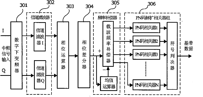
[0055] Figure 5 A block diagram showing a configuration example of an apparatus for demodulating a half-cosine shaped OQPSK or MSK modulated signal according to the second embodiment. The receiving device has a digital down converter 501, a channel filter 502, a phase operator 503, a phase differencer 504, a carrier frequency compensator and an average operator 505, a PN code code table 506, a PN code correlator 507, and a symbol decision device 508.

[0056] Figure 5 The working process of the shown demodulator is explained as follows:

[0057] The structure of the wireless transceiver system used by the demodulator adopts a low-IF structure, and the transmitting end adopts half-cosine OQPSK or MSK signal modulation, and directly spreads the binary baseband data into PN codes, and then modulates and transmits with the carrier. The receiving end is connected to the demodulator through the RF front end. The intermediate frequency signal is in the form of a complex signal, ...


PUM


Abstract

The invention proposes an incoherent frequency compensation and demodulation method and a demodulation device which have low power consumption, high performance and use the pseudo-randomness of the received signal phase and the PN code to realize the wireless digital communication data demodulation which has short distance, low power consumption and low packet loss rate through the carrier frequency error compensation and data recovery; the demodulation device is composed of a digital low-converter, a channel filter, a phase arithmetic unit, a phase differentiator, a frequency compensator and a PN code de-spreading correlator; the intermediate signal is converted into the plural baseband signals which are processed with channel outer band noise filtration so that the amplitude-time signal is converted into the phase-time signal; the phase differentiator is adopted to differentiate the phase-time signal; the frequency compensation circuit compensate the carrier frequency according to the phase difference signal and the phase average signal; the carrier frequency and the phase recovery circuit are avoided; the PN code correlator group processes the matching demodulation towards the semi-cosine shaping 0QPSK and MSK signals of the DSSS directly to recover the baseband data; the incoherent frequency compensation and demodulation method and the demodulation device has the advantages of simple circuit, less quantity of hardware, easy low power consumption integration, good demodulation performance and being applicable to the wireless satellite navigation and the short-range wireless communication device with batteries as the power supply.

Description

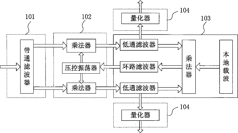
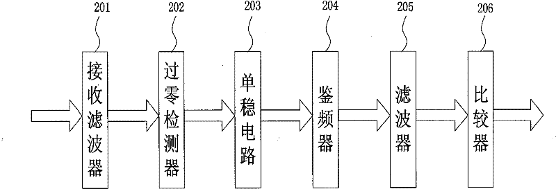
technical field [0001] The invention belongs to the technical field of wireless communication, and relates to a low-power-consumption high-performance non-coherent demodulation method suitable for half-cosine shaping OQPSK or MSK modulation method and Direct Sequence Spread Spectrum (DSSS), in particular to non-coherent frequency compensation and demodulation Tuning method and demodulation device. Background technique [0002] At present, due to the narrow signal bandwidth and good demodulation performance of the half-cosine shaped OQPSK and MSK signals, they are widely used in the field of wireless digital communication. [0003] There are two traditional half-cosine shaping OQPSK and MSK demodulation methods: one is to use a coherent demodulator, such as figure 1 shown. In the demodulation method, the out-of-band noise is filtered out through the band-pass filter 101, and then the synchronization and recovery of the carrier and phase are realized through the phase-locked...

Claims


Application Information

Patent Timeline
Patent Type & Authority Patents(China)
IPC IPC(8): H04L27/38
Inventor 肖时茂孟新于云丰马成炎叶甜春
Owner 杭州中科微电子有限公司
Learn More