Compressor casing for an exhaust gas turbocharger

A technology of compressor shell and exhaust gas turbine, which is applied to components, machines/engines, instruments, etc. of pumping devices for elastic fluids, which can solve problems such as efficiency loss, slow adjustment, time delay, etc., and reduce manufacturing costs , Simplified manufacturing, and low-cost effects

Inactive Publication Date: 2008-11-19
CONTINENTAL AUTOMOTIVE GMBH
View PDF4 Cites 6 Cited by
  • Summary
  • Abstract
  • Description
  • Claims
  • Application Information

AI Technical Summary

Problems solved by technology

However, such an adjustment is relatively sluggish, since the pressure build-up occurs with a delay when the rotational speed of the rotor exceeds
Therefore, the speed regulation for the turbocharger must be carried out by means of a corresponding early reduction of the charge pressure with charge pressure monitoring in the range of high power variation (load shift), which leads to a loss of efficiency

Method used


Image

  • Compressor casing for an exhaust gas turbocharger
  • Compressor casing for an exhaust gas turbocharger
  • Compressor casing for an exhaust gas turbocharger

Examples


Embodiment Construction

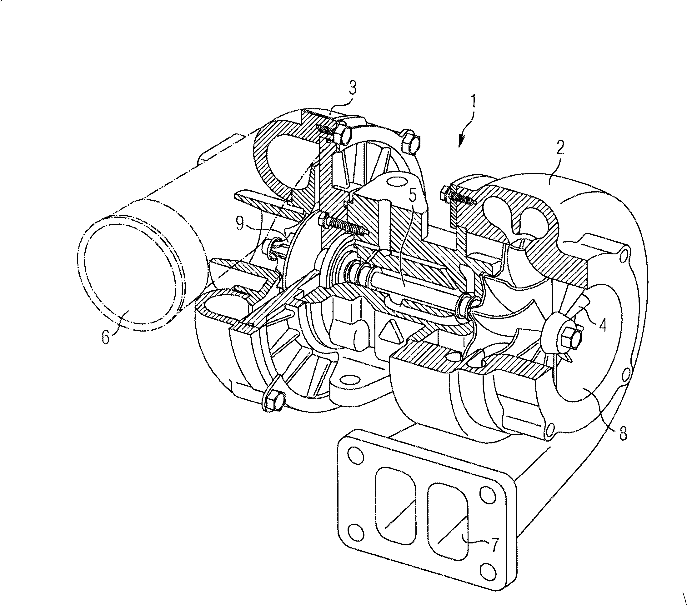
[0027] figure 1 A turbocharger 1 with a turbine 2 and a compressor 3 is shown. The compressor wheel 9 is rotatably arranged in the compressor 3 and connected to the turbine shaft 5 . The turbine shaft 5 is also arranged rotatably and is connected at its other end to the turbine wheel 4 . Hot exhaust gas (not shown) from the internal combustion engine enters the turbine 2 through the turbine inlet 7 so that the turbine wheel 4 is rotated. The exhaust flow exits the turbine 2 through the turbine exhaust 8 . The turbine wheel 4 is connected to a compressor wheel 9 via a turbine shaft 5 . The turbine 2 thereby drives the compressor 3 . Air is sucked into the compressor 3 via the air inlet 10 , compressed there, and delivered via the outlet 6 to the internal combustion engine (not shown here).

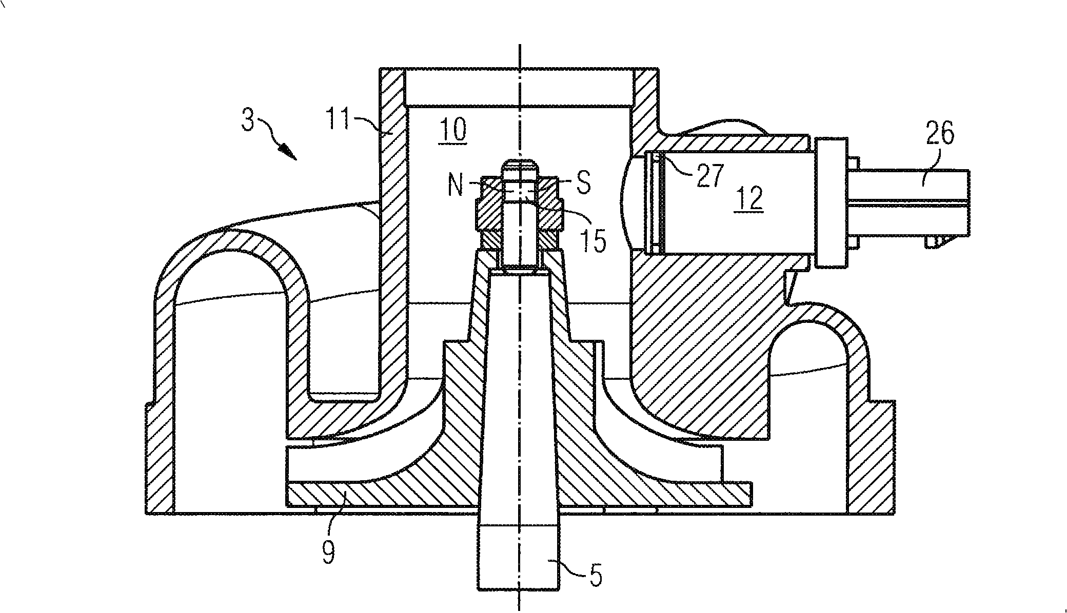
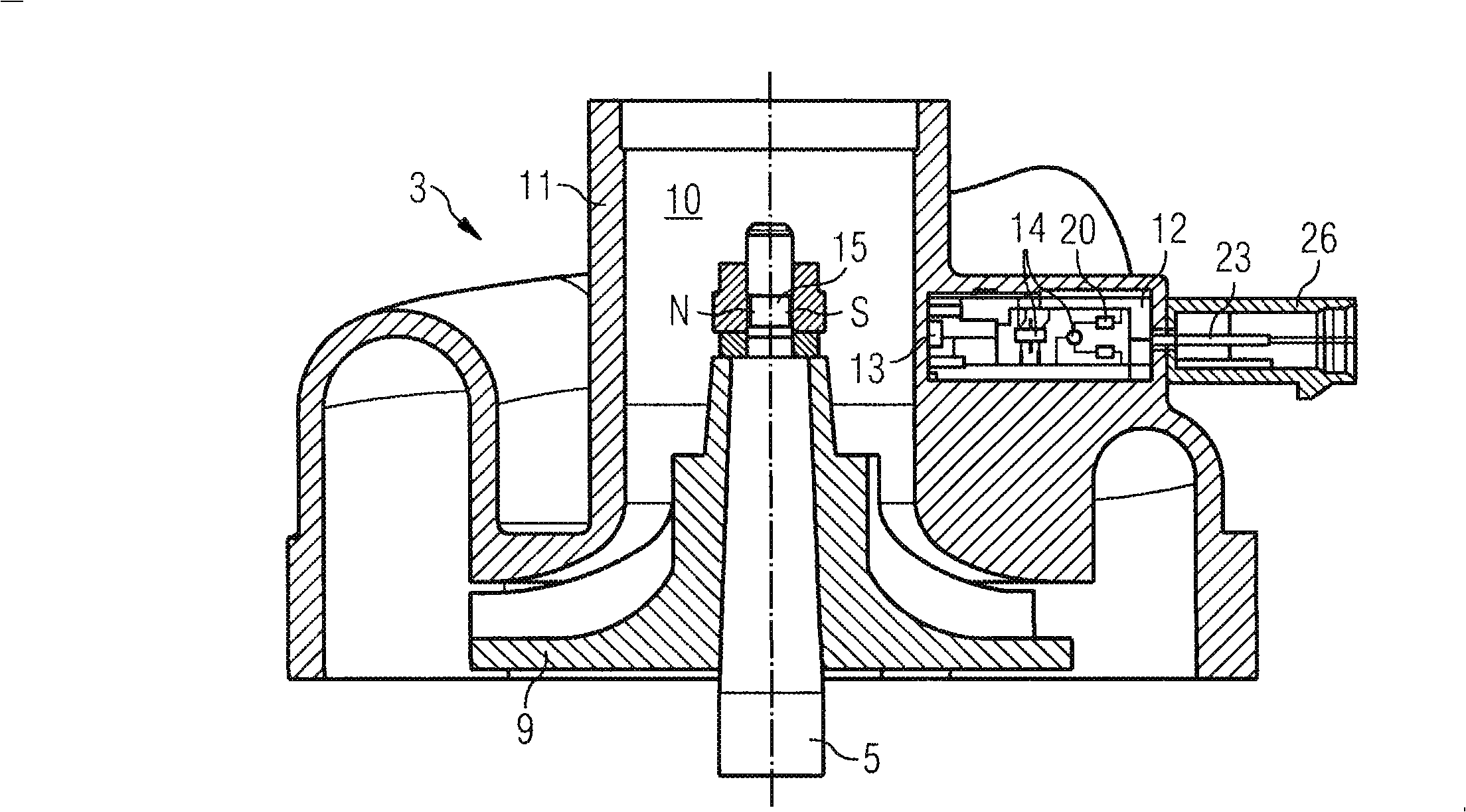
[0028] According to the existing technology, figure 2Shown is a compressor 3 of a turbocharger 1 having a sensor 12 for detecting the rotational speed of a turbine shaft 5 . The tur...


PUM


Abstract

The invention relates to a compressor casing for an exhaust gas turbocharger, said casing being produced by an injection-molding method. The exhaust gas turbocharger has a turboshaft that is mechanically connected to a compressor wheel and a turbine wheel. The invention also relates to a method for producing said compressor casing. The aim of the invention is to allow an inexpensive, reliable and exact detection of the speed of the rotating parts (turbine wheel, compressor wheel, turboshaft) of an exhaust gas turbocharger. For this purpose, a sensor for measuring the speed of the turboshaft is embedded into the compressor casing during injection molding, thereby creating a sensor that is configured as a component that is integrated into the compressor casing itself.

Description

technical field [0001] The invention relates to a compressor housing produced by injection molding for an exhaust gas turbocharger having a turbine shaft mechanically connected to a compressor wheel and a turbine wheel / turbo; and The invention also relates to a method for manufacturing the compressor housing. Background technique [0002] The power produced by the internal combustion engine depends on the air mass and the corresponding fuel quantity which are available for combustion by the internal combustion engine. In order to increase the power of the internal combustion engine, it is necessary to increase the supply of combustion air and fuel. The increase in power is achieved by increasing the working volume of the cylinder or increasing the speed in a self-priming engine. However, increasing the cylinder displacement basically results in a heavier, larger-sized and more expensive internal combustion engine. Particularly in larger internal combustion engines, an inc...

Claims


Application Information

Patent Timeline
Patent Type & Authority Applications(China)
IPC IPC(8): F01D25/24F02B37/00
CPCG01P3/487F01D17/06F02B67/10F04D27/001F04D27/0261G01P1/026F01D21/003F05D2220/40G01P3/488F01D25/24F04D29/4206Y10T29/49243Y10T29/4924Y02B30/70F04D29/40
Inventor 约翰内斯·安特马库斯·吉尔希
Owner CONTINENTAL AUTOMOTIVE GMBH
Why Eureka
Try Eureka