Vibration suppressing device and vibration suppressing method for machine tool

A technology for vibration suppression and machine tools, which is applied in the direction of automatic control devices, feeding devices, manufacturing tools, etc., can solve the problems of residual processing surface, high cost, high-priced pulse devices, etc., to suppress tool wear, prevent tool defects, and ensure finishing The effect of precision

Inactive Publication Date: 2008-11-26
OKUMA CORP +1
View PDF2 Cites 45 Cited by
  • Summary
  • Abstract
  • Description
  • Claims
  • Application Information

AI Technical Summary

Problems solved by technology

[0006] However, in the method of the above-mentioned patent document 1, when obtaining the "natural frequency", an expensive pulse device is required, so there is a problem of high cost.
In addition, the vibration method of Patent Document 1 not only requires a high level of technology, but also has the difficulty of obtaining an accurate optimum rotation speed because the "natural frequency" measured before machining does not necessarily coincide with the "natural frequency" during machining. Such a problem of poor practicality
[0007] On the other hand, in the above-mentioned method of Patent Document 2, the "flutter frequency" is obtained by analyzing the whirling sound detected by the acoustic s

Method used


Image

  • Vibration suppressing device and vibration suppressing method for machine tool
  • Vibration suppressing device and vibration suppressing method for machine tool
  • Vibration suppressing device and vibration suppressing method for machine tool

Examples


Embodiment Construction

[0023] Next, a vibration suppression device according to one embodiment of the present invention will be described with reference to the drawings.

[0024] [Method 1]

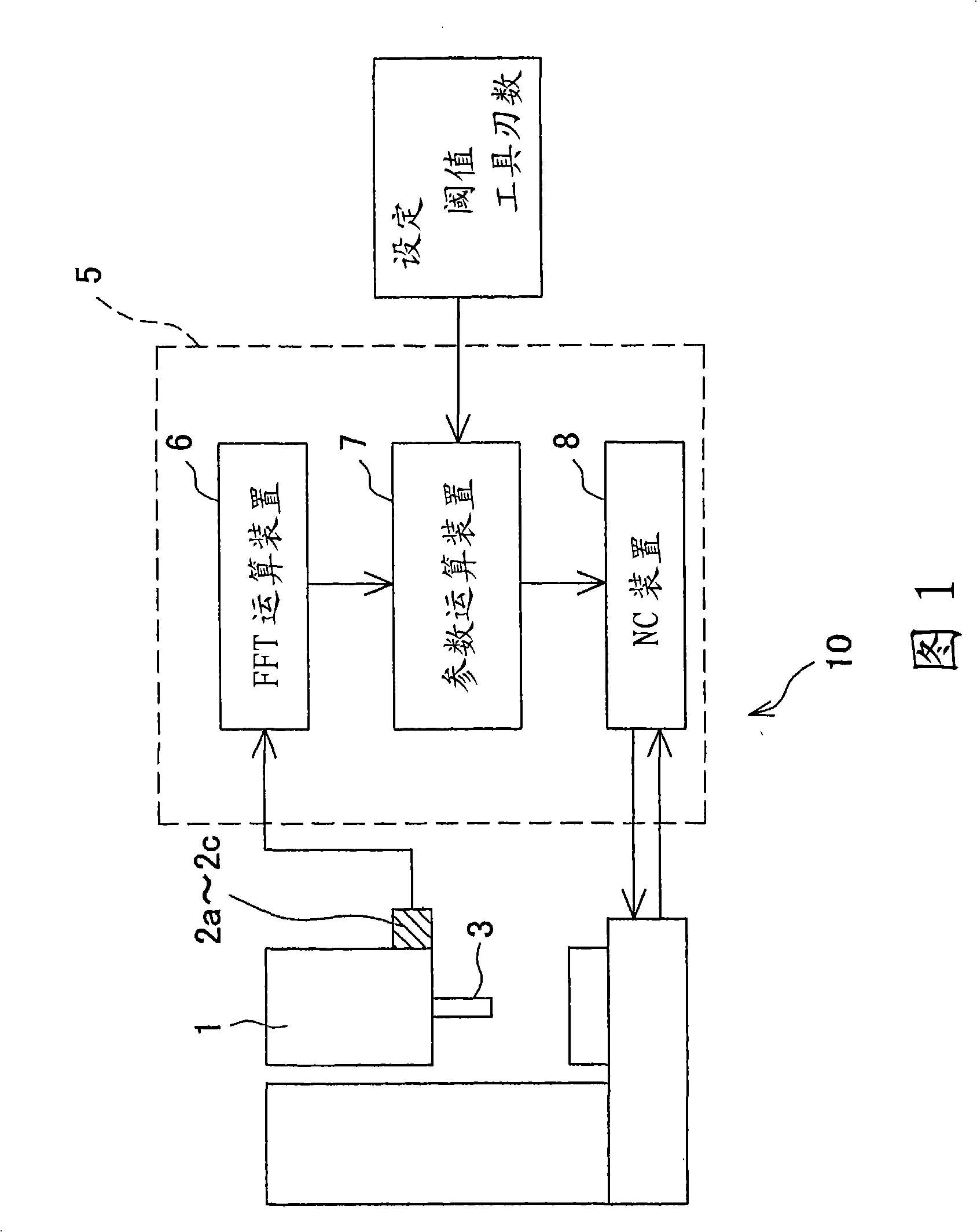
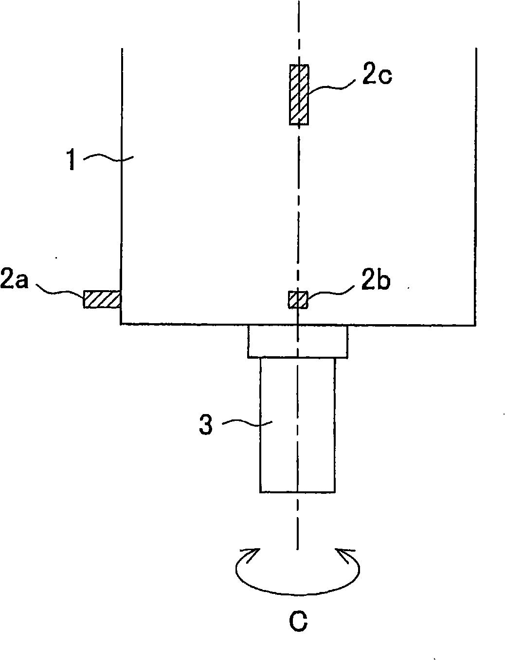
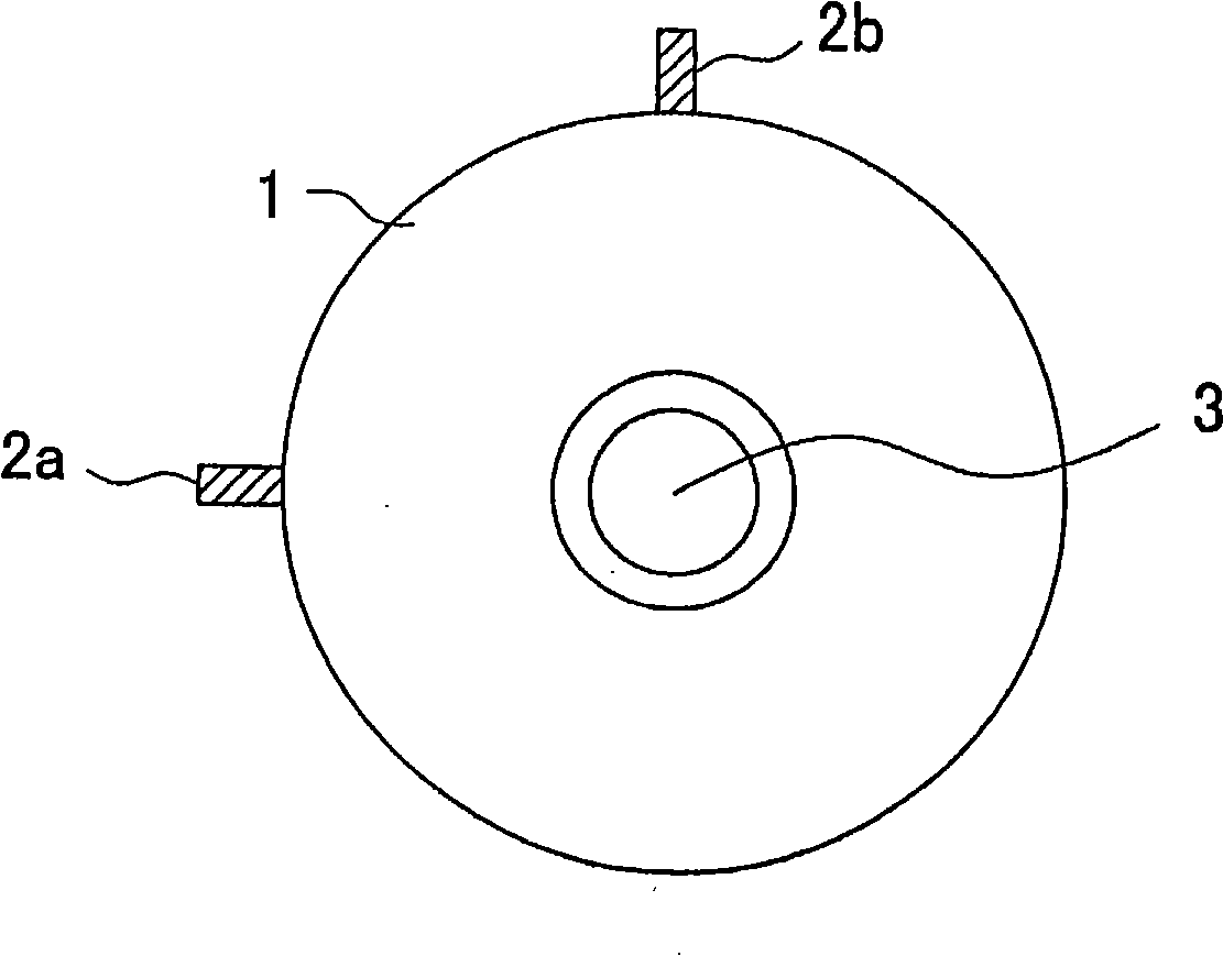
[0025] FIG. 1 is an explanatory diagram showing a frame configuration of a vibration suppressing device 10 . figure 2 It is an explanatory diagram showing the rotating shaft frame 1 to be suppressed from the side, image 3 It is an explanatory diagram showing the rotating shaft frame 1 from the axial direction.

[0026] The vibration suppressing device 10 is a device for suppressing "chatter" generated on the rotating shaft 3, which is mounted on the rotating shaft frame 1 so as to be rotatable around the C-axis, and the vibration suppressing device 10 has: a vibration sensor (Detection unit) 2a~2c, it is used to detect the vibration acceleration of the time domain that produces on the rotating shaft 3 in rotation; The detected detection value is used to control the rotational speed of the rotary shaft 3 . ...


PUM


Abstract

A vibration suppressing device and a vibration suppressing method that are capable of obtaining an accurate optimum rotation speed and shortening a time period from generation of chatter vibration to calculation of the optimum rotation speed are provided. The vibration suppressing device 10 includes: vibration sensors 2a to 2c for detecting time-domain vibrational accelerations of a rotary shaft 3 in rotation; and a control device 5 for calculating a chatter frequency and a frequency-domain vibrational acceleration of the rotary shaft 3 at the chatter frequency on the basis of the time-domain vibrational accelerations detected by the vibration sensors 2a to 2c, and when the calculated frequency-domain vibrational acceleration exceeds a predetermined threshold value, calculating an optimum rotation speed on the basis of a predetermined parameter, and rotating the rotary shaft 3 at the calculated optimum rotation speed.

Description

technical field [0001] The present invention relates to a vibration suppressing device and a vibration suppressing method for suppressing vibration generated during machining in a machine tool that performs machining while rotating a tool or a workpiece. Background technique [0002] Conventionally, for example, there is a machine tool in which a workpiece is supported on a rotatable spindle, and a tool is fed to the workpiece while processing the workpiece. In this machine tool, when the amount of cut in the cutting process is greater than necessary, so-called "chatter" occurs during machining, and there is a problem that the finishing accuracy of the machined surface is deteriorated. At this time, self-excited vibration, that is, "regenerative chatter" is particularly problematic. In order to suppress this "regenerative chatter", as described in Patent Documents 1 and 2, the following techniques are known: Find the natural vibration frequency of the system that produces "...

Claims


Application Information

Patent Timeline
IPC IPC(8): B23Q11/00B23Q15/00
CPCB23Q17/0976
Inventor 铃木教和社本英二稻垣浩
Owner OKUMA CORP
Why Eureka
Try Eureka