Wound electric double-layer capacitor

An electric double layer capacitor, wound type technology, applied in the manufacture of hybrid/electric double layer capacitors, electrolytic capacitors, capacitors, etc., can solve the problem of less deterioration of characteristics, and achieve the effect of less deterioration of characteristics and high reliability

Active Publication Date: 2008-12-03
PANASONIC CORP
View PDF3 Cites 11 Cited by
  • Summary
  • Abstract
  • Description
  • Claims
  • Application Information

AI Technical Summary

Problems solved by technology

[0025] The present invention provides a wound-type electric double layer capacitor with high performance, which solves the conventional p...

Method used


Image

  • Wound electric double-layer capacitor
  • Wound electric double-layer capacitor
  • Wound electric double-layer capacitor

Examples


no. 1 approach

[0060] Next, the first embodiment will be described.

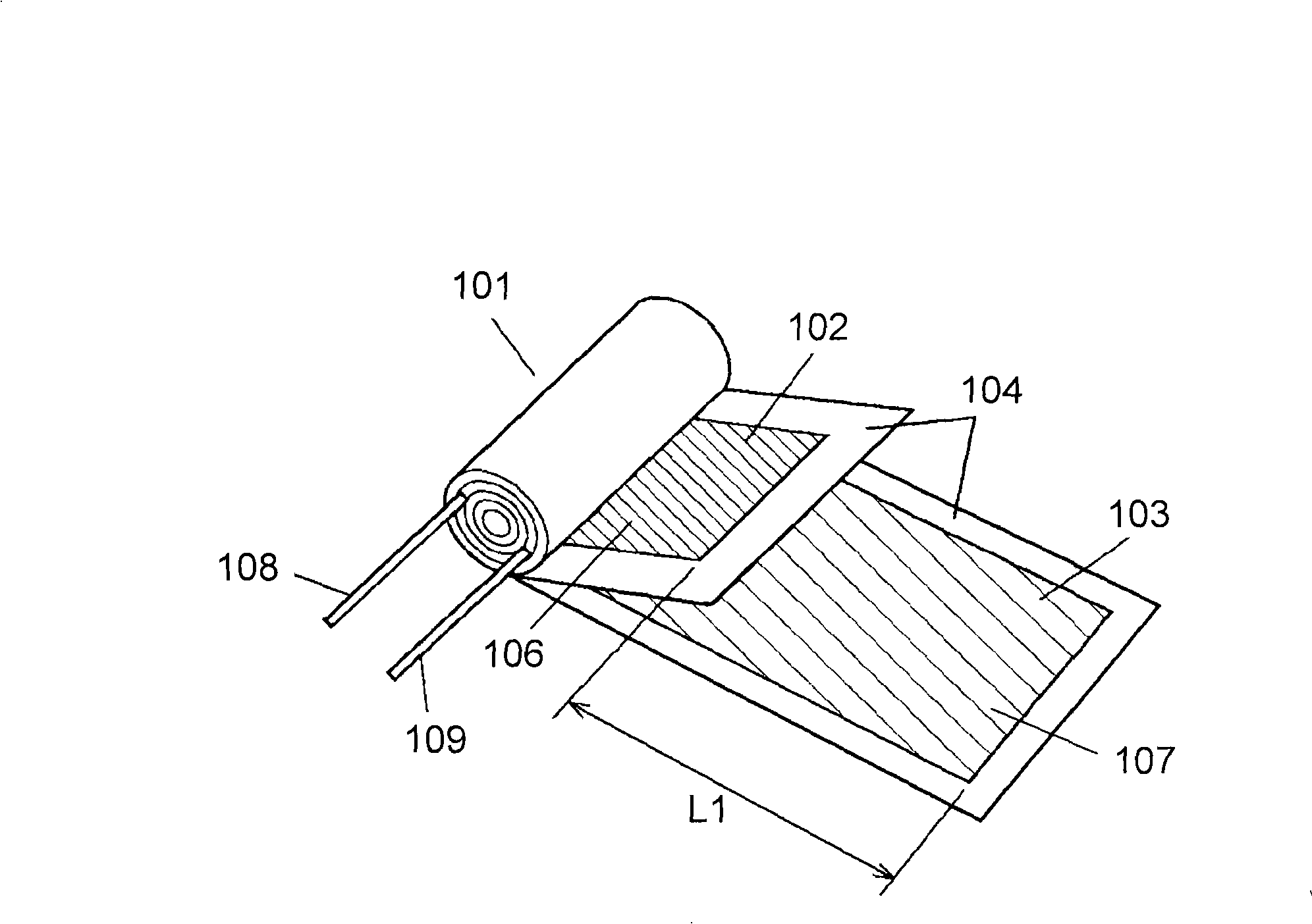
[0061] figure 1 It is a developed perspective view showing the configuration of a capacitor element used in the wound electric double layer capacitor of the first embodiment. figure 1 Among them, the capacitor element 101 is wound with the separator 104 interposed between the anode electrode 102 and the cathode electrode 103 .

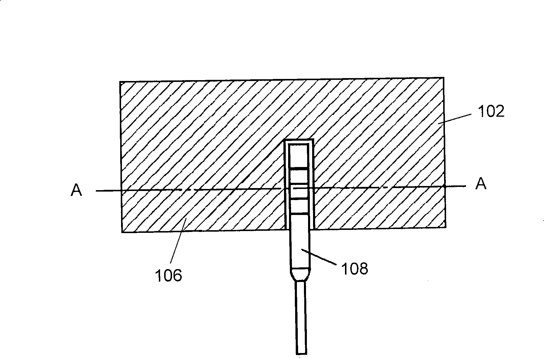
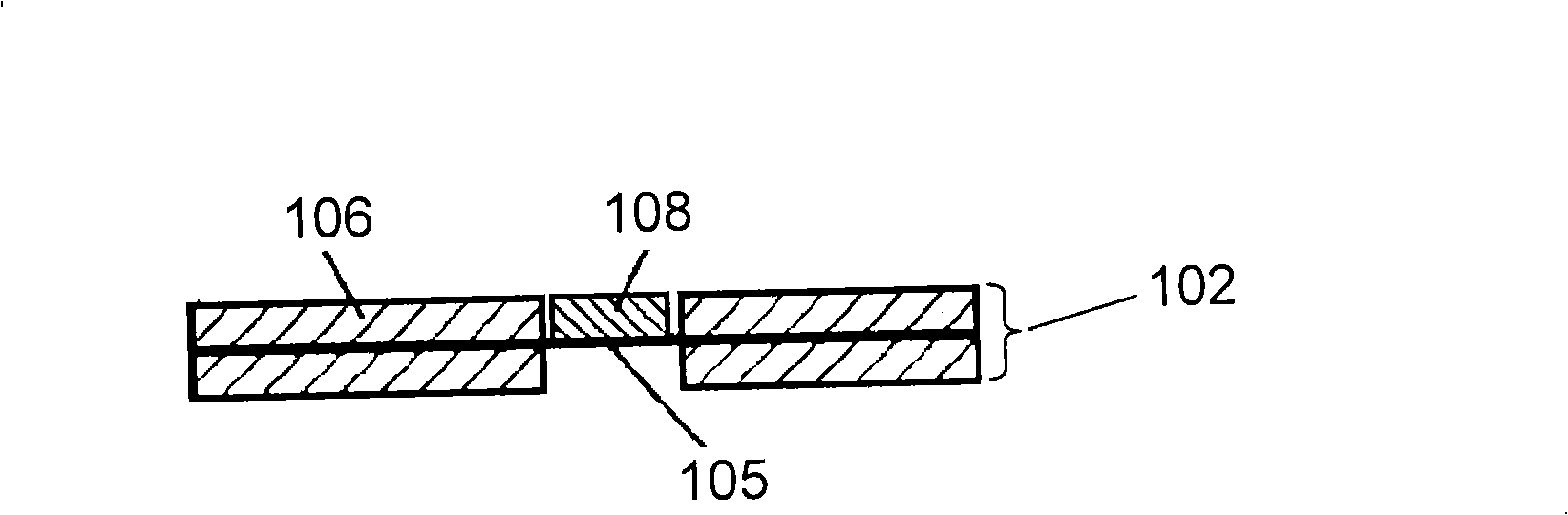
[0062] In addition, the above-mentioned anode electrode 102 and cathode electrode 103 are formed by forming polarizable electrode layers 106 or 107 respectively on both surfaces of a current collector 105 composed of a metal foil described later. Furthermore, the anode electrode 102 and the cathode electrode 103 are connected to an anode lead 108 and a cathode lead 109 , respectively. The details of the connection of the anode lead 108 and the cathode lead 109 are as follows Figure 2A , Figure 2B As shown, a part of the polarizable electrode layer 106 formed on the anode electrode 102 (the ...

no. 1 example

[0072] As a current collector composed of metal foil, a high-purity aluminum foil (AL: 99.99% or more) with a thickness of 30 μm was used, and electrolytic etching was performed in a hydrochloric acid-based etching solution to roughen the surface of the aluminum foil.

[0073] Next, polarizable electrode layers were formed on both sides of the aluminum foil. The polarizable electrode layer is formed by mixing phenolic resin-based activated carbon powder with an average particle size of 5 μm, carbon black with an average particle size of 0.05 μm as a conductivity-imparting agent, and dissolved CMC water-soluble binder solution, and kneaded fully with a kneader, then add a dispersion solvent of methanol and water little by little, and knead again to make a slurry with a specified viscosity. Next, this slurry was applied on the surface of the aluminum foil, and dried in the air at 100° C. for one hour to form a polarizable electrode layer.

[0074] Next, the aluminum foil formed...

no. 2 example

[0080] In the first embodiment above, if image 3 The anode electrode and the cathode electrode are arranged as shown, and the width W2 of the cathode electrode is set to 44 mm with respect to the width W1 (40 mm) of the anode electrode. The rest is the same as that of the first embodiment to produce a wound electric double layer capacitor.


PUM

PropertyMeasurementUnit
Thicknessaaaaaaaaaa

Abstract

The present invention provides a wound electric double-layer capacitor having less-deteriorating characteristics and a high reliability realized by preventing the electro-chemical reaction on the polarizable electrode layer surface. The wound eclectic double-layer capacitor comprises a capacitor element fabricated by exposing a part of the polarizable electrode layers formed on both sides of the current collector, connecting anode and cathode lead wires to the exposed part, interposed a separator between the anode and the cathode, and winding them, a metal case containing the capacitor element and a driving electrolyte, and a sealing member sealing the opening of the metal case. At least one turn of the cathode from the end of the wound anode is further wound. Thereby, at the outside periphery the capacitor element has a part where the polarizable electrode layer formed on the cathode is opposed to itself with the separator interposed between them.

Description

technical field [0001] The present invention relates to wound electric double layer capacitors used in various electronic devices. Background technique [0002] Figure 10A is an exploded perspective view showing the structure of such a conventional wound electric double layer capacitor, Figure 10B It is an expanded perspective view showing the structure of the capacitor element used for this capacitor. Figure 10A , Figure 10B Among them, the capacitor element 431 is constituted by winding a separator 436 between the anode electrode 434 and the cathode electrode 435 . [0003] Also, the anode electrode 434 and the cathode electrode 435 are constituted by forming polarizable electrode layers (not shown) respectively on both surfaces of a current collector (not shown) composed of metal foil, and the anode electrode 434 and the The cathode electrode 435 is connected to the anode lead 432 and the cathode lead 433, respectively. [0004] In addition, the capacitor element 4...

Claims


Application Information

Patent Timeline
IPC IPC(8): H01G9/058H01G9/008H01G9/016H01G9/048H01G11/22H01G11/24H01G11/26H01G11/38H01G11/42H01G11/44H01G11/66H01G11/68H01G11/70H01G11/74H01G11/78H01G11/86
CPCH01G9/048H01G9/008H01G9/016Y02E60/13H01G11/74
Inventor 广瀬惠理高向芳典伊藤靖幸大西聪都美
Owner PANASONIC CORP
Why Eureka
Try Eureka