Anode and battery
A negative electrode current collector and negative electrode technology, applied in the direction of secondary batteries, battery electrodes, lithium storage batteries, etc., can solve the problems of secondary battery discharge capacity decrease, secondary battery manufacturing yield decrease, secondary battery cycle characteristics degradation, etc. , to achieve the effect of improving cycle characteristics and manufacturing yield
- Summary
- Abstract
- Description
- Claims
- Application Information
AI Technical Summary
Problems solved by technology
Method used
Image

Examples
Embodiment 1-1
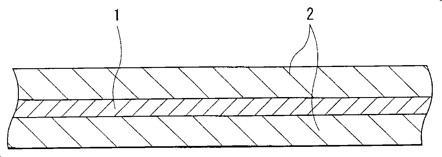
[0135] Manufactured by the following steps Figure 8 with Figure 9 The laminated film type secondary battery shown. At this time, the laminated film type secondary battery is a lithium ion secondary battery in which the capacity of the negative electrode 54 is expressed based on insertion and extraction of lithium.
[0136] First, the positive electrode 53 is formed. Mix lithium carbonate (Li 2 CO 3 ) and cobalt carbonate (CoCO 3 ), the mixture was calcined in air at 900°C for 5 hours to obtain a lithium cobalt composite oxide (LiCoO 2 ). Next, after mixing 91 parts by weight of lithium-cobalt composite oxide as the negative electrode active material, 6 parts by weight of graphite as the conductive agent and 3 parts by weight of polyvinylidene fluoride as the binder to form the positive electrode mixture, the positive electrode mixture was dispersed in N -Methyl-2-pyrrolidone, thereby forming a pasty positive electrode mixture slurry. Finally, the positive electrode m...
Embodiment 1-2~1-12
[0142] Form the secondary battery by the same steps as in Example 1-1, the difference is that the peak aperture is 100nm (Example 1-2), 120nm (Example 1-3), 150nm (Example 1-4), 200nm (Example 1-5), 300nm (Example 1-6), 400nm (Example 1-7), 500nm (Example 1-8), 600nm (Example 1-9), 800nm (Example 1-9) 10), 1000nm (Examples 1-11) or 1200nm (Examples 1-12) instead of 80nm.
Embodiment 2-1~2-12
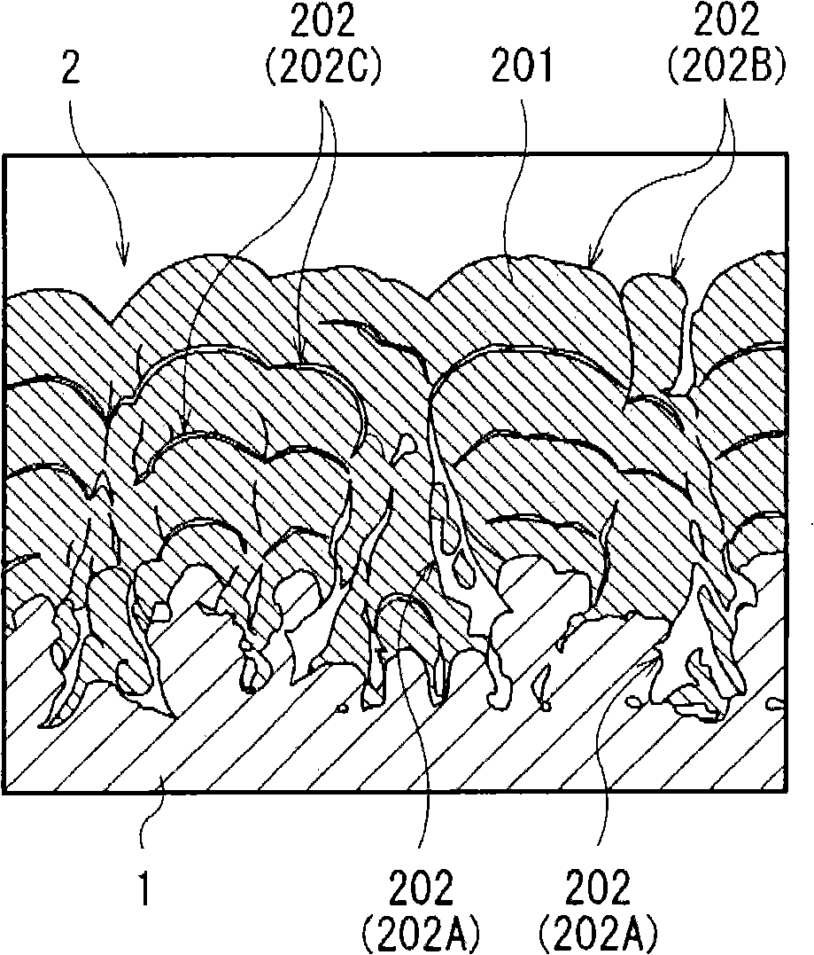
[0158] A secondary battery was formed through the same steps as in Examples 1-1 to 1-12, except that the negative electrode active material had a six-layer structure. In the case of forming the anode active material, silicon was continuously deposited for lamination while the anode current collector 54A moved back and forth relative to the evaporation source at a deposition rate of 100 nm / s.
PUM
| Property | Measurement | Unit |
|---|---|---|
| roughness | aaaaa | aaaaa |
| aperture size | aaaaa | aaaaa |
| aperture size | aaaaa | aaaaa |
Abstract
Description
Claims
Application Information
 - R&D
- Intellectual Property
- Life Sciences
- Materials
- Tech Scout
- Unparalleled Data Quality
- Higher Quality Content
- 60% Fewer Hallucinations
Browse by: Latest US Patents, China's latest patents, Technical Efficacy Thesaurus, Application Domain, Technology Topic, Popular Technical Reports.
© 2025 PatSnap. All rights reserved.Legal|Privacy policy|Modern Slavery Act Transparency Statement|Sitemap|About US| Contact US: help@patsnap.com