
Dual Crystal Forward Active Clamp Switching Power Supply

A clamping switch and clamping capacitor technology, which is applied in the field of dual-crystal forward active clamping switching power supplies, can solve the problems of low core utilization, power and efficiency limitation, damage, etc., and achieve the improvement of core utilization, The effect of voltage stress reduction and volume reduction

Inactive Publication Date: 2012-02-01
DONGGUAN YIHENG ELECTRONICS
View PDF5 Cites 1 Cited by
  • Summary
  • Abstract
  • Description
  • Claims
  • Application Information

AI Technical Summary

Problems solved by technology

But it also has some disadvantages: the transformer is unidirectionally magnetized, the utilization rate of the magnetic core is low, and the volume is too large. At the same time, due to the reset of the magnetic core, its duty cycle cannot be greater than 0.5, and the frequency of the switch tube can not work in the hard switching state. too high
However, its disadvantages are: in high-voltage applications, the main switch tube requires a high withstand voltage. The higher the withstand voltage of the existing power tube process, the smaller the current and the larger the on-resistance, so the power and efficiency are limited, and the duty ratio control is not accurate. Catastrophic damage, another disadvantage is the need for precise control of synchronization delay time technology
[0004] Obviously, the above two methods are no longer able to meet the needs of various developments.

Method used


Image

  • Dual Crystal Forward Active Clamp Switching Power Supply
  • Dual Crystal Forward Active Clamp Switching Power Supply
  • Dual Crystal Forward Active Clamp Switching Power Supply

Examples


Embodiment Construction

[0023] The following content is a further detailed description of the present invention in conjunction with specific preferred embodiments, and it cannot be assumed that the specific implementation of the present invention is limited to these descriptions. For those of ordinary skill in the technical field of the present invention, without departing from the concept of the present invention, some simple deduction or replacement can be made, which should be regarded as belonging to the protection scope of the present invention.

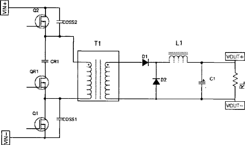
[0024] see figure 1 , the dual crystal forward active clamp switching power supply of the present invention includes a primary part, a transformer T1 and a secondary part.

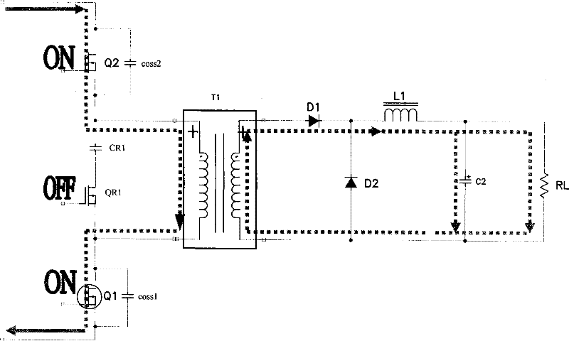
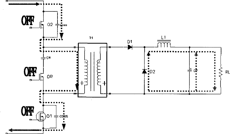
[0025] The primary part includes a first main switch tube Q1 , a clamp switch tube QR1 , a clamp capacitor CR1 and a second main switch tube Q2 . The D pole of the second main switching tube Q2 is connected to the input power supply, the S pole is connected to the same-named term...


PUM


Abstract

A dual crystal forward active clamp switching power supply of the present invention includes a primary part, a transformer and a secondary part, wherein the primary part includes a first main switching tube, a clamping switching tube, a clamping capacitor and a second main switching tube, The D pole of the second main switching tube is connected to the input power supply, the S pole is connected to the same-named end of the primary winding of the transformer, the D pole of the first main switching tube is connected to the different-named end of the transformer primary winding, and the S pole is connected to the input One end of the clamping capacitor is connected to the same-named terminal of the transformer, the other end is connected to the D pole of the clamping switch tube, and the S pole of the clamping switch tube is connected to the different-named terminal of the transformer.

Description

technical field [0001] The invention relates to a switching power supply, in particular to a double crystal forward active clamping switching power supply. Background technique [0002] Existing switching power supplies mainly include dual crystal forward and single crystal forward active clamp. Among them, the dual-crystal forward adopts a double-tube forward converter, which has a simple structure, low voltage stress of the switch tube, automatic reset of the magnetic core, and returns the energy of the leakage inductance to the input power supply, with high reliability, and can be used in high-voltage, medium-power, and high-power applications. Wide range of applications. However, it also has some disadvantages: the transformer is unidirectionally magnetized, the utilization rate of the magnetic core is low, and the volume is too large. At the same time, due to the reset of the magnetic core, its duty cycle cannot be greater than 0.5, and the frequency of the switch tube...

Claims


Application Information

Patent Timeline
Patent Type & Authority Patents(China)
IPC IPC(8): H02M7/12H02M3/07
Inventor 刘小荷
Owner DONGGUAN YIHENG ELECTRONICS
Learn More