
High precision thrust force centripetal combined conical roller bearing

A tapered roller bearing and thrust centripetal technology, which is applied in the field of bearings, can solve the problems that cannot meet the high precision and high rigidity of CNC vertical lathe, achieve the effect of light weight, good processing technology, and eliminate clamping errors

Active Publication Date: 2010-12-08
成都科华重型轴承有限公司
View PDF7 Cites 1 Cited by
  • Summary
  • Abstract
  • Description
  • Claims
  • Application Information

AI Technical Summary

Problems solved by technology

[0005] The high-precision thrust centripetal combined tapered roller bearing proposed by the present invention is to solve the above-mentioned six existing slewing bearing structures, which cannot meet the high precision, high rigidity and higher speed ( >60rpm) Requirements

Method used


Image

  • High precision thrust force centripetal combined conical roller bearing
  • High precision thrust force centripetal combined conical roller bearing
  • High precision thrust force centripetal combined conical roller bearing

Examples


Embodiment 1

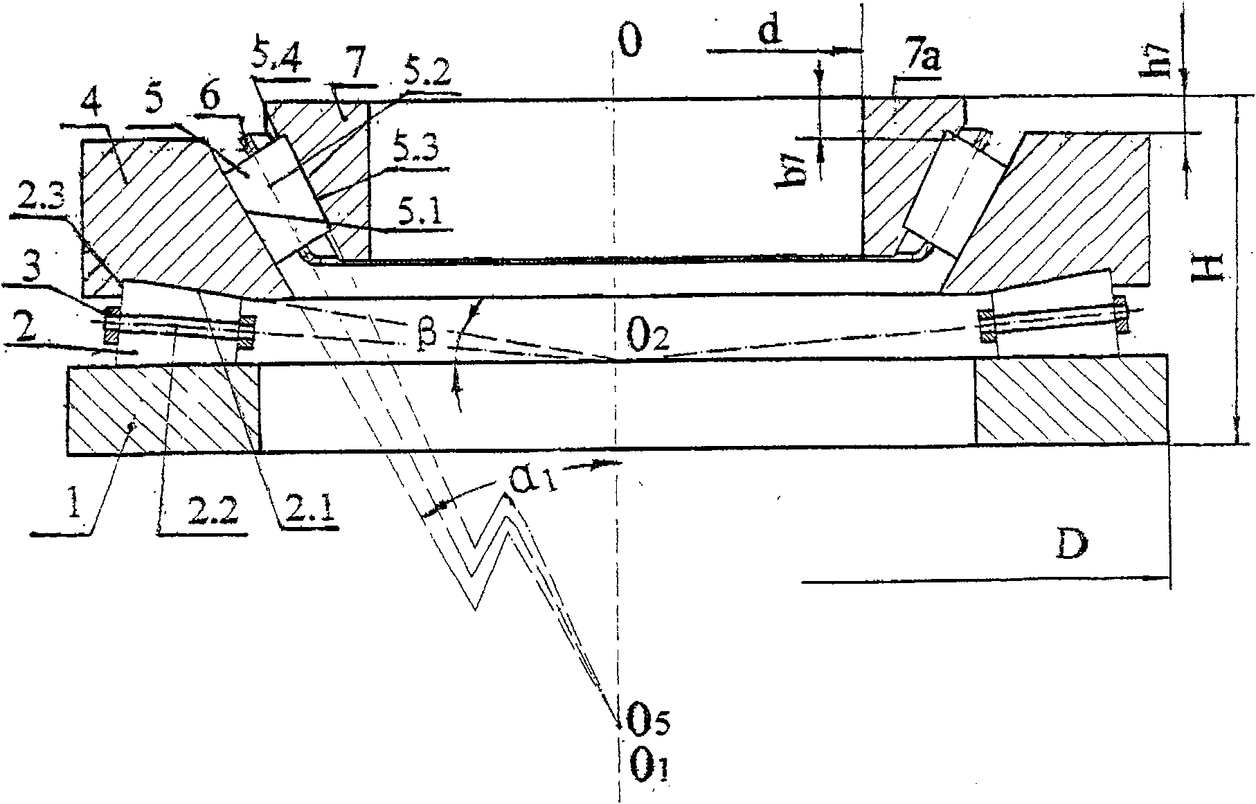
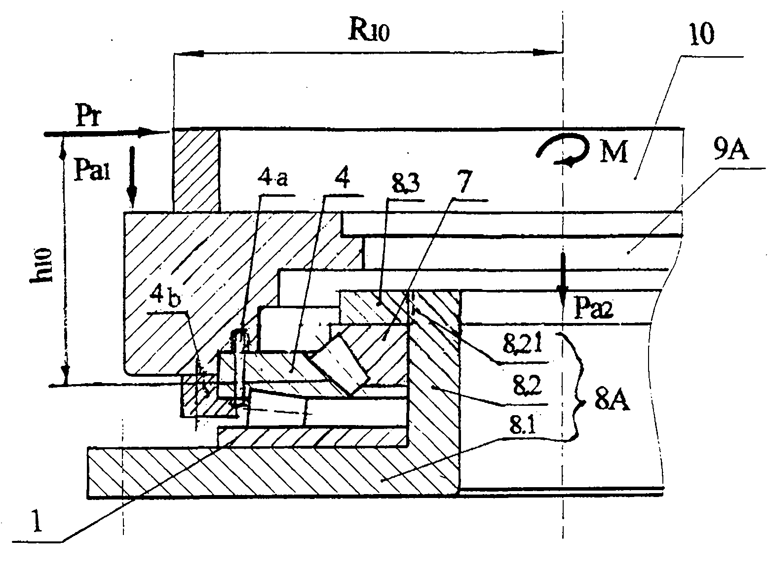
[0031] Embodiment 1: the present embodiment 1 bearing (see figure 1 ) is applied to the vertical car turntable (see image 3 ).

[0032] See figure 1 , there is a static thrust race 1 and a moving coil 4, a number of thrust tapered rollers 2 and a cage 3 for isolating rollers 2 are installed between the two rolling surfaces; the moving coil 4 has a lower raceway of the moving ring and a roller The road busbar 2.1, the thrust rib and the rib busbar 2.3 form a thrust tapered roller bearing bearing axial load. There is a stationary conical inner ring 7, and several centripetal thrust tapered rollers 5 and cages 6 for isolating rollers 5 are installed circumferentially between its outer raceway 5.1 and the moving ring 4; the moving ring 4 has an upper raceway and Raceway bus 5.1, conical inner ring 7 has ribs and rib bus 5.4; thereby forming a radial thrust tapered roller bearing bearing radial load. Cages 3 and 6 can use pillar cage 3, and when small-sized rollers can also u...

Embodiment 2

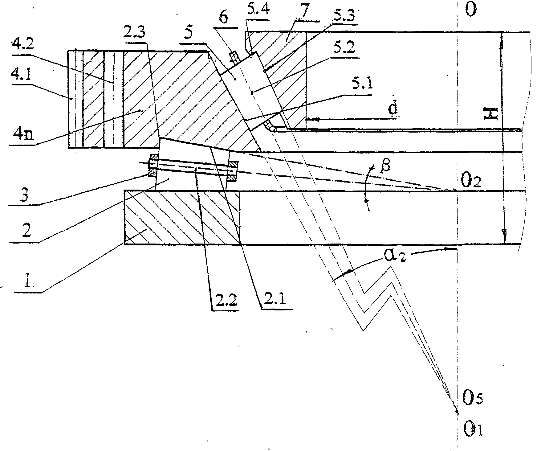
[0036] Example 2: see figure 2 , Figure 4

[0037] This embodiment 2 bearings (see figure 2 ) applied to high-precision turntable bearing turntable (see Figure 4 ), that is, a radar device for long-range high-precision positioning. Embodiment 2 bearing except the following structure and characteristics and embodiment 1 (see figure 1 ) are different, the rest are exactly the same:

[0038] See figure 2 , ① The moving coil is replaced by 4n figure 1 The moving coil 4, that is, outer teeth 4.1 and connecting holes 4.2 matched with the application equipment are arranged on the outer periphery. ② Centripetal raceway busbar 5.1 and bearing axis line OO 1 Angle α 2 Take it as 40°~60°. If a larger angle α is chosen 2 The radial bearing capacity of the combined bearing will be greatly reduced.

[0039] See Figure 4 , Embodiment 2 After the bearing is installed in the radar device, the relevant structure is as follows: the static thrust race 1 and the inner ring 7 a...


PUM


Abstract

The invention relates to a high-precision thrust centripetal combined tapered roller bearing, which is provided with a thrust block seat ring and a movable ring; a thrust tapered roller and a retaining frame are arranged between the thrust block seat ring and the movable ring; a centripetal thrust tapered roller and a retaining frame are arranged between a static inner ring and a movable ring, thereby combining a thrust tapered roller bearing for bearing axial load and a centripetal thrust tapered roller bearing for bearing radial load into a whole. The high-precision thrust centripetal combined tapered roller bearing realizes a capacity of bearing large thrust and large centripetal load; and a pressure adjusting ring is arranged to produce zero or negative clearance to meets the requirements that a numerical control vertical lathe has high precision, high rigidity and a rotating floor with a high rotational speed. Compared with the prior good three-row puncheon bearing of the INA corporation, the weight of the high-precision thrust centripetal combined tapered roller bearing is only 89.7 percent; but the axial load and the radial movable load are respectively 3.7 times and 2.1 times; and the axial static load and the radial static load are respectively 2.864 times and 1.54 times. As a raceway and a block side generatrix use special design, the tapered roller bearing removes the skid of the roller and has low operating temperature and high limit speed. The structure is used to process an inside diameter, the raceway, the block sides, etc. by once positioning and clamping and has high rotating precision; the radial jumping kinetic energy and the axial jumping kinetic energy can reach less than or equal to 3 mu m. The high-precision thrust centripetal combined tapered roller bearing can be used for a high-precision numerical control vertical lathe, a vertical milling and rotating floor, a radar rotating floor, etc.

Description

[0001] (1) Technical field: The present invention relates to a thrust radial tapered roller bearing, which belongs to the bearing category (F16C). (two) background technology: [0002] Check the existing rolling bearing data at home and abroad, the structure of the slewing bearing is as follows: ① four-point contact single row ball slewing bearing. ② Four-point contact double row ball slewing bearing. ③ Two-point contact double row ball slewing bearing. ④Cross cylindrical roller slewing bearing (single row). ⑤Cross tapered roller slewing bearing (single row). ⑥Three-row short cylindrical roller slewing bearing. [0003] Slewing bearings are widely used in equipment that is required to withstand large axial forces and overturning moments, such as: lifting cranes, tower cranes, stackers and reclaimers, ladle turrets, artillery turrets, radar turrets, pitch and yaw supports for wind power generation. These slewing bearings have high load carrying capacity but low precision an...

Claims


Application Information

Patent Timeline
Patent Type & Authority Patents(China)
IPC IPC(8): F16C19/50F16C33/58F16C33/46
CPCF16C19/38F16C19/385F16C19/381
Inventor 文鉴恒
Owner 成都科华重型轴承有限公司
Learn More