Power supply switch and control device for implementing nought power consumption standby

A zero-power consumption standby and control device technology, applied to computer control, power device inside the switch, program control, etc., to achieve the effect of simple structure and production process, low cost and reliable performance

Inactive Publication Date: 2011-12-21
袁想平
View PDF3 Cites 2 Cited by
  • Summary
  • Abstract
  • Description
  • Claims
  • Application Information

AI Technical Summary

Problems solved by technology

[0005]3. Add a small single-chip microcomputer specially for the processing of infrared remote control. After judging that the command is correct, open or cut off the original AC circuit through the electromagnetic relay, and the single-chip microcomputer itself uses a battery or supercapacitor to supply power to achieve the so-called "zero power consumption standby". Internal battery power supply) or even less than a few tenths of a watt of power consumption, but because of its common feature is "the normally open contacts of the electromagnetic relay are connected in series in the AC circuit, and the electromagnetic coil is energized and maintained to connect to the AC power supply when starting up." , the electromagnetic relay is released after the remote control is turned off, and the AC power is cut off". This method does achieve full cut-off of the AC power and zero-power standby after standby, but it also has some important shortcomings:
[0006]a. Increase the power consumption of one or two sets of coils (some patents use an intermediate relay plus a power relay). However, this power consumption cannot be ignored during work. For example, the power consumption of the coil itself for driving a 250V / 5-8A electric shock relay in the AC main circuit is between 0.4W-0.8W, that is to say, If the technology is applied, although it can save power after shutdown, it increases the power consumption by 0.3-0.5W×2 during normal operation, so this is a false energy saving, which cannot achieve the real energy saving effect;
[0007]b. In this method, after the voltage on the battery or capacitor is exhausted, a special switch is required to force the power on, which makes the user's operation complicated;
[0008]c. Only after the original push-button power switch is closed can the remote controller be used to switch the machine on and off. Pressing it by hand in front of the face does not achieve perfect operability, that is, the user can use any one of the power button, remote control, and light touch standby button to turn on or off at any time, regardless of where the controlled device is. a state;
[0009]d. The added circuits and parts increase the failure rate and unreliability of the controlled equipment, especially when the battery self-discharges, the contacts and coils of the relay If it is powered on for a long time, it is easy to overheat and burn out, and the single-chip microcomputer may be disturbed and malfunction. Due to the feature of "adding a normally open contact of a relay connected in series in the AC circuit" similar to this technology, once any part of it fails, it will cause it to be blocked. All functions of the control device are lost and cannot be turned on;
[0010]4. Add a small single-chip microcomputer specially for infrared remote control processing. After judging that the command is correct, connect or cut off the original AC circuit through the electromagnetic relay. The processing process is the same as the method 3 is very similar, but the power supply of the single-chip microcomputer is obtained by rectifying and filtering the AC power. Since the single-chip microcomputer is very power-saving, this method can achieve a standby power below 0.1-1W. Since its core technology is similar to method 3, its disadvantages are also similar, except No battery or capacitor drain issues

Method used


Image

  • Power supply switch and control device for implementing nought power consumption standby
  • Power supply switch and control device for implementing nought power consumption standby
  • Power supply switch and control device for implementing nought power consumption standby

Examples


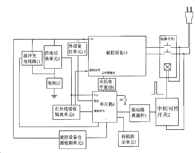
Embodiment Construction

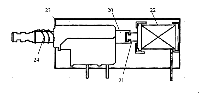
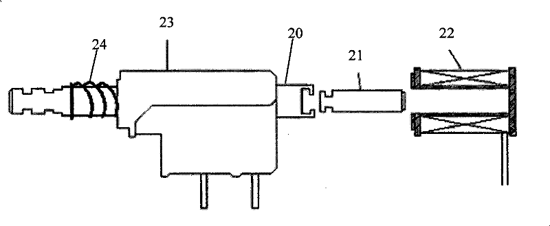
[0044] The action of the power switch of the present invention is described below:

[0045] 1. Apply pulse current to make it connected: when the solenoid coil 22 is fed with pulse current, the iron core 21 will make a pull-in linear motion along the direction in which the push rod 20 is pushed in, driving the self-locking button push rod 20 Push in, the self-locking shrapnel locks the switch in the closed position, and the switch contacts remain connected after the pulse current ends;

[0046] 2. Apply pulse current to make it disconnect: when the solenoid coil 22 is fed with pulse current, the iron core 21 makes a pull-in linear motion along the pushing direction of the push rod 20, driving the self-locking button push rod 20 Push in, the self-locking shrapnel locks the switch in the off position, and the switch contacts remain open after the pulse current ends.

[0047] The above operation process is similar to manually pressing the push rod 20. After the power switch is t...


PUM


Abstract

The invention relates to a power switch for realizing zero standby power consumption and a control device. The control device comprises an SCM and a power switch connected between controlled equipment and an input power; the interior of the power switch is provided with a coil and an iron core. After the SCM receives the instruction of startup or shutdown, an instant impulse signal is output for controlling the conduction of a drive switch; an instant impulse current is generated in the coil of the power switch; the iron core under the effect of the magnetic force generated by the coil connects or disconnects the input power of the controlled equipment. Aiming at solving the disadvantage that the realization of zero standby power consumption increases extra power consumption of the prior art in normal working hours, thereby being unable to realize real effect of energy saving, the invention provides the power switch for realizing zero standby power consumption and the control device, and therefore, in standby state or in normal working state, no current passes through the coil of the power switch, realizing real zero power consumption and energy saving.

Description

technical field [0001] The invention relates to household appliances, more specifically, to a control device for realizing zero power consumption standby. Background technique [0002] In the current household appliances such as TV sets, users mostly turn off the power through the remote control, which is what we often call "standby". In this case, the power supply, remote control receiving and microprocessor parts in the machine still keep working to ensure that the electrical appliances can be woken up from the remote control or the light touch button on the machine next time. The power supply and microprocessor are designed for the whole system under full load, and the power consumption after standby is still maintained at a relatively high level. In addition, the circuit of the whole machine is connected to the power grid when it is in standby, so there are certain safety hazards, such as fire or explosion caused by lightning strike or overvoltage. Reducing standby en...

Claims


Application Information

Patent Timeline
Patent Type & Authority Patents(China)
IPC IPC(8): G05B19/042H01H13/50H01H3/28H01H13/20
Inventor 袁想平
Owner 袁想平
Why Eureka
Try Eureka