Control and regulation device for safeguarding a conveyor device, conveyor device and crane unit

A technology for controlling and adjusting conveyors, applied to cranes, hoisting devices, clockwork mechanisms, etc., can solve the problems of expensive hydraulic control sliding structures and large maintenance

Active Publication Date: 2008-12-31
PINTSCH BUBENZER
View PDF1 Cites 4 Cited by
  • Summary
  • Abstract
  • Description
  • Claims
  • Application Information

AI Technical Summary

Problems solved by technology

This hydraulically controlled sliding structure is very expensive and requires a lot of maint

Method used


Image

  • Control and regulation device for safeguarding a conveyor device, conveyor device and crane unit
  • Control and regulation device for safeguarding a conveyor device, conveyor device and crane unit
  • Control and regulation device for safeguarding a conveyor device, conveyor device and crane unit

Examples


Embodiment Construction

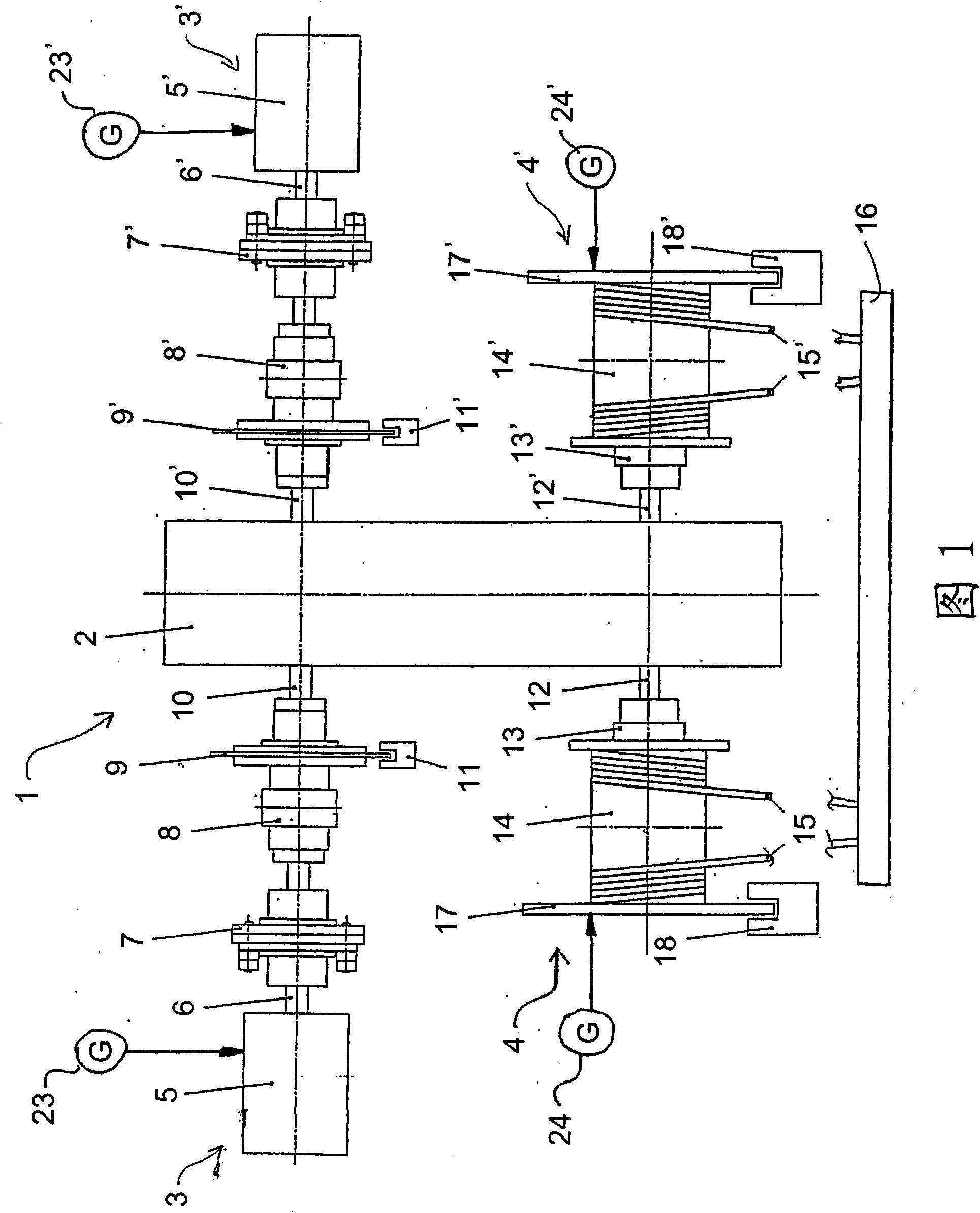
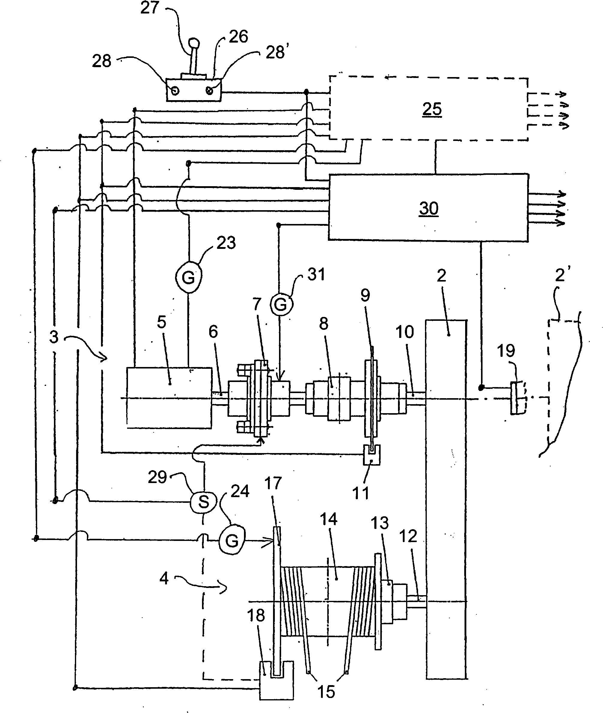
[0024] The lifting device 1 shown in Figure 1 comprises two cable-operated hoists and has, in combination with a gear transmission 2, forming two drive and driven systems (3, 3', 4, 4' respectively). In the following description the main elements of the power path system will be described, and in the drawings their corresponding parts are indicated by reference numerals on the left and by the same reference numerals on the right, the latter being distinguished by an apostrophe.

[0025] The drive motor 5, 5' rotates the drive shaft 6, 6' to activate the overload coupling 7, 7', where the torque is further transmitted through a conventional coupling 8, 8' which in turn is connected to the brake Disc 9, 9'. The part 10, 10' of the drive shaft provides power to the gear transmission 2. Said brake discs 9, 9' are managed by brake calipers 11, 11' (hereinafter referred to as "service brakes"). The output shafts 12, 12' of the gear transmission 2 act via couplings 13, 13' on ...


PUM


Abstract

The invention relates to a control and regulation device for safeguarding a conveyor device (1), in particular, a crane unit in the case of overload. A brake device (11, 18) acting on the conveyor device (1) is provided, along with a controller (30) for the brake device (11, 18), an overload sensor (29), recording the overload and emitting an overload signal and a speed sensor (31, 24), recording a cA process for the production of iohexol comprises alkylating 5-Acetamido-N,N'-bis(2,3-dihydroxypropyl)-2,4,6- triiodoisophthalamide using 2(2-methoxy-ethoxy)-ethanol as solvent in the presence of a base, and optionally isolating crude iohexol from the reaction mixture. Preferably, the alkylating agent is 1-chloro-2,3 propanediol and the base is an alkali metal hydroxide such as sodium hydroxide or potassium hydroxide.onveyed item speed and emitting a speed signal. The controller (30) reacts to the overload signal on the braking device (11, 18), such that this device stops the conveyor device and thus safeguards a conveyed item (16).; On a subsequent unload signal the controller (30) releases the conveyor device (1) such that the conveyor device (1) is moved into an unload position by the effect of the load of the conveyed item (16) and the effect of the braking device (11, 18) on the conveyor device (1) is regulated according to the speed signal from the speed sensor (24, 31) such that the conveyed item (16) is moved into the unload state at an essentially constant conveyor speed. The invention further relates to a conveyor device with such a control and regulation arrangement and a container crane unit with two conveyor devices provided with such a control and regulation device.

Description

technical field [0001] The invention relates to a control regulation structure for the protection of conveyors such as cranes with lifting and structural elements. The control structure is designed to provide a protective reaction when conveying overload is detected. That is, the control comes into play when the delivery load exceeds a predetermined threshold. Particularly in the case of cranes, lifts or other vertical lifting devices, said overloading occurs when the lifted object being transported is too heavy and / or the lifted object engages or becomes lodged in the surrounding structure itself. With hoisting cranes in particular, there is the danger that, while the load is in an upward lifting movement, it is restrained by fixed objects intruding into its defined path of motion. In this case, hoist overloading can occur, which can dangerously damage the lifting equipment, or, if a self-erecting crane is involved, the crane can tip over from its rest position. Backgroun...

Claims


Application Information

Patent Timeline
IPC IPC(8): B66C23/90B66D1/58
CPCB66D1/26B66D1/58
Inventor 德克·浮士德
Owner PINTSCH BUBENZER
Why Eureka
Try Eureka