
Heat exchanger

A heat exchanger and heat exchange tube technology, applied in the direction of heat exchanger types, indirect heat exchangers, lighting and heating equipment, etc., can solve problems such as reducing heat exchange efficiency, low efficiency of heat exchanger use, and affecting reuse. , to reduce production costs and operating costs, improve heat exchange efficiency, and achieve a wide range of applications.

Inactive Publication Date: 2009-01-07
王元平
View PDF0 Cites 13 Cited by
  • Summary
  • Abstract
  • Description
  • Claims
  • Application Information

AI Technical Summary

Problems solved by technology

[0003] 1. The thermal conductivity of various materials used in existing heat exchange tubes is generally low, which makes the heat exchange efficiency low, which leads to large heat exchanger equipment, which makes the operating cost and production cost too high;
[0004] 2. Heat exchange tubes are prone to fouling and clogging, and their service life is short, requiring frequent maintenance, often resulting in production shutdown losses;
[0005] 3. Metal materials such as steel and aluminum cannot resist the corrosion of chemicals in some cases, and the use occasions are limited;
[0006] 4. The sealing effect of the existing heat exchanger is poor, and liquid leakage is prone to occur, so that the existing heat exchanger cannot use materials with better heat exchange performance such as silicon carbide, and the pressure bearing is generally relatively low, which cannot meet the high-pressure liquid exchange. thermal requirements;
[0007] 5. The existing heat exchange tubes are slow to return to normal temperature after use, which affects their re-use, resulting in low efficiency of the heat exchanger;
[0008] 6. There is often air in the heat exchanger, which leads to uneven heat transfer effect and reduces heat transfer efficiency;
[0009] 7. After the heat exchanger is used for a period of time, heavy impurities in the heat exchange medium liquid accumulate in the heat exchanger, which reduces the heat exchange efficiency and easily damages the heat exchanger;

Method used


Image

  • Heat exchanger
  • Heat exchanger

Examples


Embodiment Construction

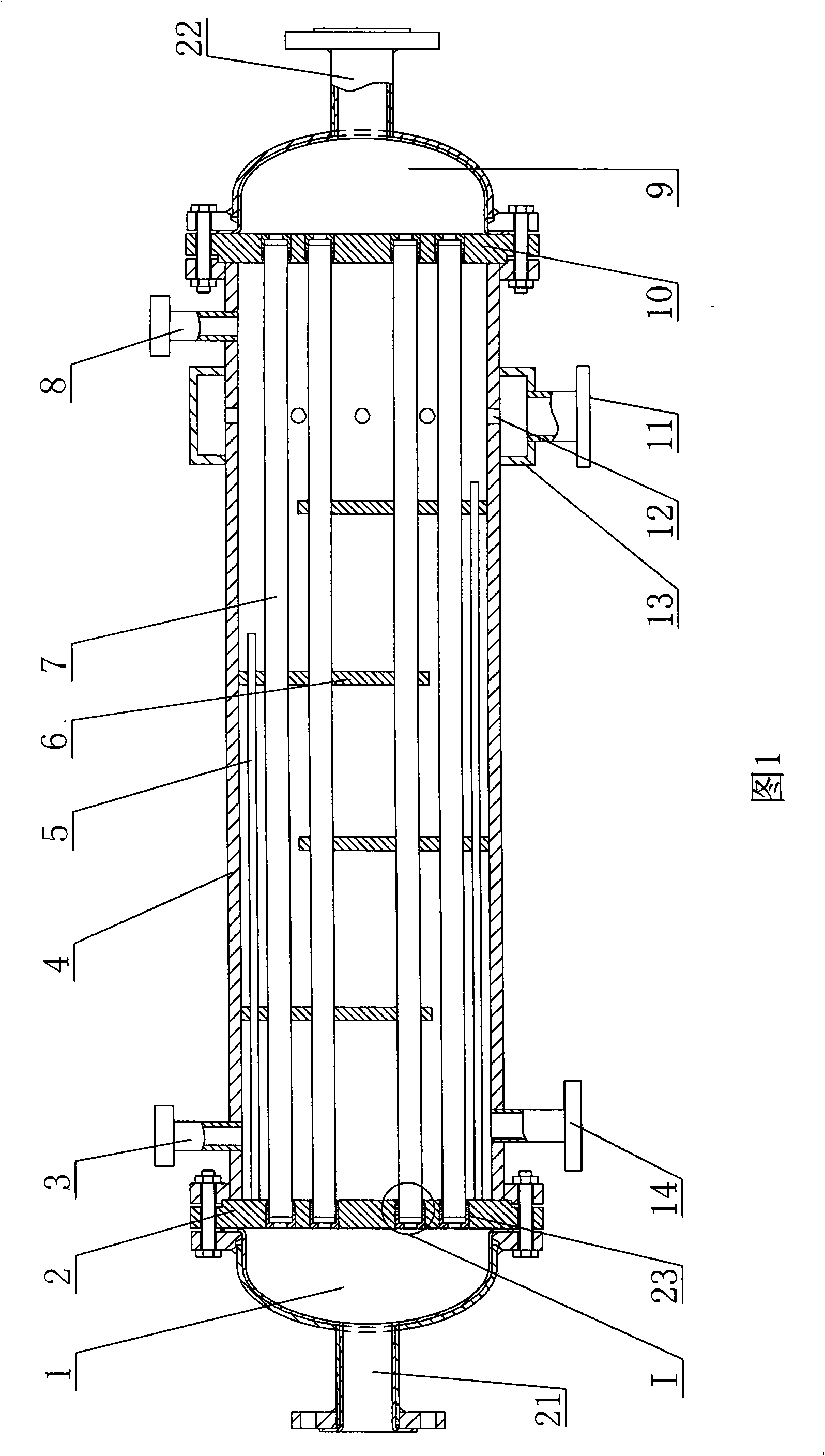
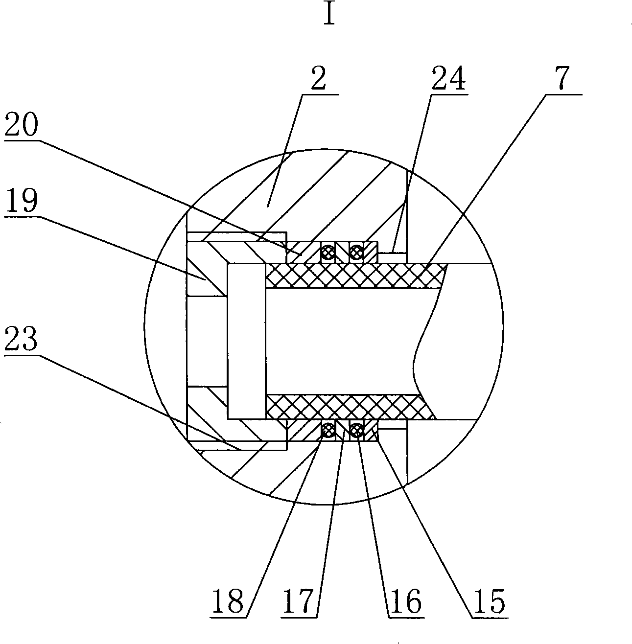
[0014] The present invention includes a tube shell 4, which is a barrel-shaped hollow structure. The tube shell 4 can be made of different materials according to the medium liquid used, such as carbon steel or stainless steel. The first tube plate 2 and the second tube plate 10 are respectively installed at both ends of the tube shell 4, the first head 1 is installed on one side of the first tube plate 2, the second head 9 is installed on the side of the second tube plate 10, and the first seal A first liquid outlet 21 is provided on the head 1 , and a second liquid outlet 22 is provided on the second head 2 . The first tube sheet 2 and the second tube sheet 10 are provided with corresponding through holes 23 , and the heat exchange tubes 7 are installed in the through holes 23 . The heat exchange tube 7 is made of silicon carbide or silicon nitride. The number of heat exchange tubes 7 is determined according to the liquid flow rate, and generally 5-10 heat exchange tubes are...


PUM


Abstract

The invention discloses a heat exchanger which comprises a pipe shell. An outlet pipe is arranged on the upper side of the pipe shell. An inlet pipe is arranged on the lower side of the pipe shell. Both ends of the pipe shell are provided with pipe sheets. An end plate is arranged on one side of each pipe sheet. The pipe sheets are provided with clear openings corresponding to each other. Heat exchange tubes are arranged in the clear openings and communicated with the end plates. The heat exchange tubes are made of carborundum or silicon nitride. Glands are arranged inside the clear openings. The glands are connected with the outside diameter of one end of the heat exchange tubes; lug bosses are arranged on the inner side of the clear openings; multi-stage sealing devices are arranged between the glands and the lug bosses. The heat exchanger has the advantages that the heat diffusivity of the heat exchange tubes is very high, thus significantly improving the production efficiency; the dust does not deposit on the heat exchange tubes which are not blocked therefore; under the condition of the same production efficiency, the size of the heat exchanger is significantly reduced due to the improvement of the heat exchange efficiency, thus reducing the manufacturing cost and the running cost; the multi-stage sealing element is adopted, thus significantly improving the seal effect.

Description

technical field [0001] The invention relates to the field of heat exchange equipment, in particular to a heat exchanger for heat exchange of corrosive liquids. Background technique [0002] In nuclear power plants, seawater desalination, salt chemical industry, steel and other fields, it is often necessary to condense, cool, heat, and evaporate some highly corrosive liquids. Corrosion-resistant heat exchangers are required in these processes. The heat exchange tubes of heat exchangers used in the market are mainly made of polytetrafluoroethylene, graphite, steel, aluminum, special metals, etc. Although these materials can play a certain anti-corrosion effect, they are currently used in use. There are still many problems with the heat exchanger: [0003] 1. The thermal conductivity of various materials used in existing heat exchange tubes is generally low, which makes the heat exchange efficiency low, which leads to large heat exchanger equipment, which makes the operating ...

Claims


Application Information

Patent Timeline
IPC IPC(8): F28D7/10
Inventor 王元平杨勇
Owner 王元平
Learn More