Multi-electrode rotary arrester switch for high-voltage impulse power source

A technology of high-voltage pulse power supply and spark gap switch, which is applied in the direction of rotary spark gap, spark gap, circuit, etc., to achieve the effect of improving stability and reliability, convenient disassembly and maintenance, and reliable opening and closing

Inactive Publication Date: 2009-01-07
BEIJING JIAOTONG UNIV
View PDF0 Cites 10 Cited by
  • Summary
  • Abstract
  • Description
  • Claims
  • Application Information

AI Technical Summary

Problems solved by technology

[0004] The technical problem to be solved by the present invention is to overcome the main problems existing in the existing spark gap switch and provide a multi-electrode rotary spark gap switch for high voltage pulse power supply

Method used


Image

  • Multi-electrode rotary arrester switch for high-voltage impulse power source
  • Multi-electrode rotary arrester switch for high-voltage impulse power source
  • Multi-electrode rotary arrester switch for high-voltage impulse power source

Examples


Embodiment 1

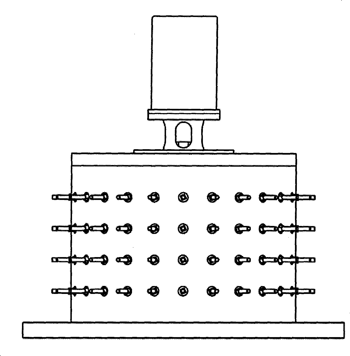
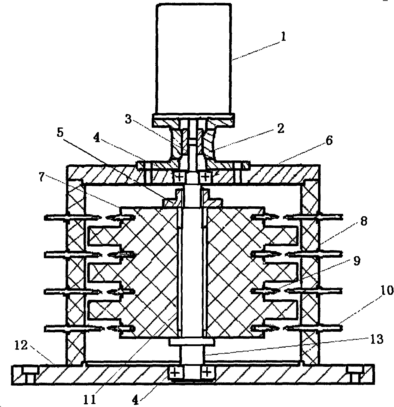
[0042]Multi-electrode rotary spark gap switch for high-voltage pulse power supply (suitable for high voltage > 20Kv, compact structure) (such as figure 1 ), the switch includes: stator 8, rotor 7, rotor needle electrode 9, stator needle electrode 10, drive motor 1, shaft 13, bearing 4, coupling 3, coupling sleeve 2, upper end cover 6, lower end cover 12.

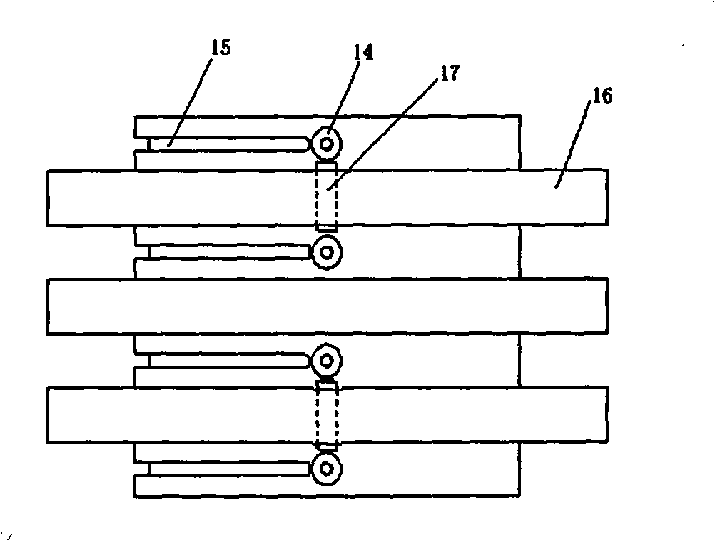
[0043] Four layers of stator needle electrodes 10 and rotor needle electrodes 9 are respectively installed on the stator 8 and the rotor 7 through screw connections. Let d be the insulation distance between the upper and lower needle electrodes of the stator. In order to ensure the reliable operation of the switch, d should satisfy d ≥ U ( kV ) 30 × 40 ( mm ) , Where U (kV) is the switch operating volta...

Embodiment 2

[0054] The four-switch multi-electrode rotary spark gap switch is suitable for high voltage < 20kV and compact structure. Its structure is the same as that of the two-switch multi-electrode rotary spark gap switch in Embodiment 1, except that the wire connection method is different.

[0055] Four layers of needle electrodes are respectively installed on the stator 8 and the rotor 7 . Let d be the insulation distance between the upper and lower needle electrodes of the stator. In order to ensure the reliable operation of the switch, d should satisfy d ≥ U ( kV ) 30 × 40 ( mm ) , Where U (kV) is the switch operating voltage.

[0056] On the stator 8, 24 stator needle electrodes 10 are evenly installed on each layer, which are divided into two groups, and the...


PUM


Abstract

The invention discloses a multi-electrode rotary spark gap switch used for a high-voltage pulse powder supply, and belongs to the technical field of pulse power. The switch comprises a stator (8), a rotor (7), a rotor needle electrode (9), a stator needle electrode (10) and a drive motor (1). The stator (8) and the rotor (7) are respectively provided with 2N layers of the needle electrodes, each layer of the stator (8) is provided with M stator needle electrodes (10), the stator needle electrodes are connected with a lead to keep the same electric potential, one rotor needle electrode (9) is arranged at each layer of the rotor (7), the rotor needle electrodes of two adjacent layers keep a 180-degree mechanical angle, and are directly connected with a lead to keep the same electric potential, and the switch is turned on when the motor drives the rotor to rotate until the rotor needle electrode and the stator needle electrode are opposite. The switch has the advantages of high switching voltage, high switching power and high frequency of repetitive work, fast switching speed less than 10ns, simple insulation structure, long service life, convenient maintenance, low cost, etc.

Description

technical field [0001] The invention relates to a high-voltage high-repetition-frequency switch for high-voltage pulse power supplies. It is used in the study of dielectric properties of dielectrics, wastewater treatment and waste gas treatment. Background technique [0002] Pulse power technology is an electrophysical technology that stores energy at a lower power for a longer period of time, and then releases energy to a specific load at a higher power in a shorter period of time. compress on. The high-voltage pulse power supply is a key device in the pulse power system. Its function is to generate high-voltage and high-instantaneous power pulses. It generally consists of three parts: energy storage device, high-voltage switch and load. The high-voltage switch is the core component of the high-voltage pulse power supply. , the performance of the high-voltage switch directly determines the overall performance of the power supply. [0003] In recent years, high-voltage pu...

Claims


Application Information

Patent Timeline
Patent Type & Authority Applications(China)
IPC IPC(8): H01T7/00
Inventor 田付强王毅雷清泉
Owner BEIJING JIAOTONG UNIV
Why Eureka
Try Eureka