
Position control method and device based on H type structure two-sided driving system

A technology of bilateral driving and positioning method, which is applied in the direction of photolithography process exposure device, microlithography exposure equipment, etc., can solve the problems of phase inconsistency, restricting the performance of control mode, and unable to feedback, so as to reduce position error and improve dynamic performance. Does not match the parameters and achieves the effect of precise positioning

Active Publication Date: 2009-01-14
SHANGHAI MICRO ELECTRONICS EQUIP (GRP) CO LTD
View PDF0 Cites 19 Cited by
  • Summary
  • Abstract
  • Description
  • Claims
  • Application Information

AI Technical Summary

Problems solved by technology

The parallel control method is the independent control of the bilateral motors, which do not interact with each other, and the disturbance on either side will not affect the other side. However, once a disturbance occurs on one side, due to the lack of mutual feedback, it belongs to open-loop control. At this time, the synchronization of the system will be difficult to guarantee
At this time, the Rz axis is generally used to correct this out-of-synchronization, but this method not only adds one more control axis, but also causes the position deviation phase of the two synchronous axes to be inconsistent, which also affects the control accuracy.
The master-slave control method can improve the tracking performance of the controller. The position of any master and the disturbance of the load can be accurately reflected on the slave. The slave can accurately track the master, but the disturbance on the slave cannot be fed back to the master, and The speed of the latter motor lags slightly behind that of the former one, and the following performance during the start-up process is not ideal, which restricts the improvement of the performance of this control method

Method used


Image

  • Position control method and device based on H type structure two-sided driving system
  • Position control method and device based on H type structure two-sided driving system
  • Position control method and device based on H type structure two-sided driving system

Examples


Embodiment Construction

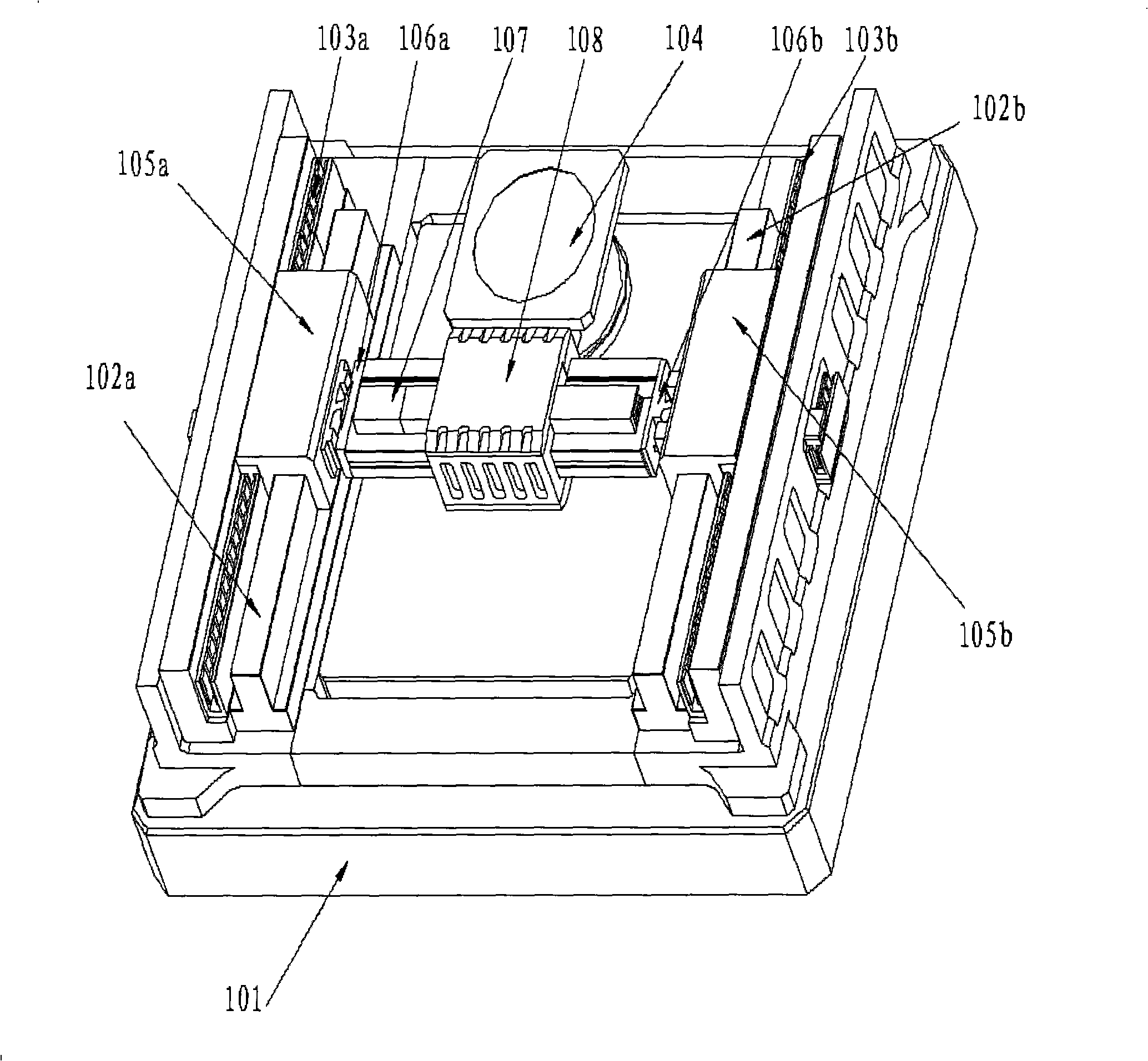
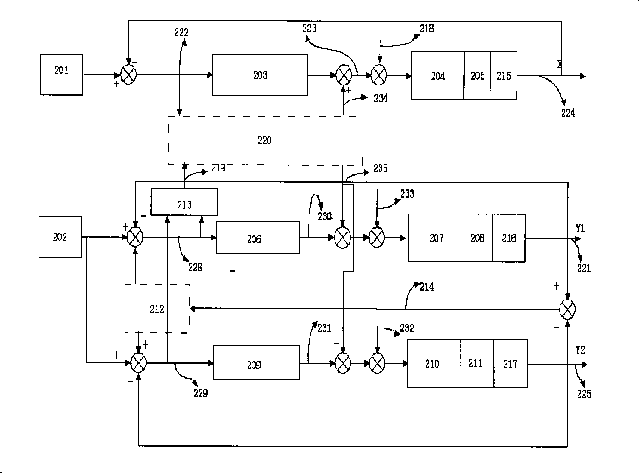
[0069] The present invention involves the bilateral synchronous control of two linear motors in the Y direction. In bilateral drive control, the outputs of the two servo systems are coupled together through the crossbeam and the X motor, and the two motors are driven to move according to the same given signal. There is no direct coupling relationship on the electrical parameters. In an ideal state, assuming that the various performances of the two linear motors are exactly the same, and the loads acting on them are completely symmetrical, then when the same command is input, the two motors should move with the same acceleration, speed, and displacement. However, in actual situations, the performance of any two motors will not be completely the same, and the dynamic changes of the two loads caused by the movement of the X-direction linear motor on the beam cause the speed of the motors to change, which causes The position is not synchronized. In order to make the servo system retur...


PUM


Abstract

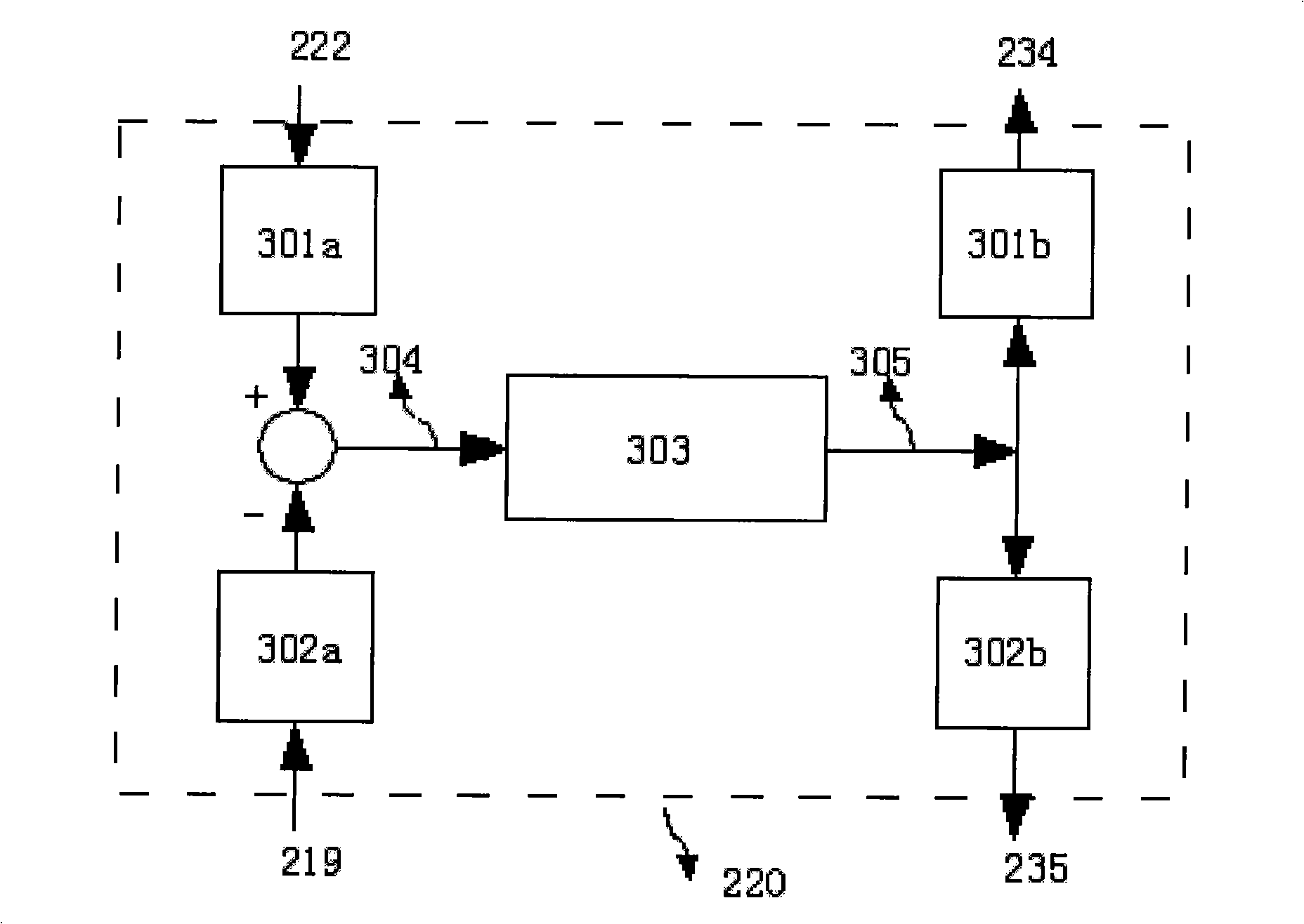
The invention provides a locating method and a corresponding apparatus used for an H-shaped drive structure. An X direction linear motor is adopted to realize an X axis movement and a Y1Y2 double-linear motor is adopted to realize a Y axis movement; the cross-coupling of two motors, namely, Y1 and Y2, is adopted to realize the control of reducing relative position errors; the cross-coupling of X axis and Y axis is adopted to realize the control of reducing contour errors; the control to the cross-coupling of three linear motors is adopted to reduce synchronous position errors and contour errors so as to realize the requirement of adopting the double-drive to synchronously control the accurate locating.

Description

Technical field [0001] The invention relates to a lithography equipment in the field of semiconductor frontiers, and in particular to a positioning control method and device of a bilateral drive system in a lithography machine. Background technique [0002] The silicon wafer production process includes a series of extremely complex, expensive, and time-consuming photolithography processes, and the lithography accuracy and yield of the lithography machine directly determine the design and manufacturing of the lithography equipment. As the market's demand for lithography productivity increases, it is also required to improve and improve the exposure quality and accuracy of the system. In this context, the actuator is required to still have high positioning accuracy when moving at high inertia and high speed. [0003] At present, the main methods of bilateral synchronous drive are parallel control and master-slave control. Parallel control method is the independent control of bilate...

Claims


Application Information

Patent Timeline
IPC IPC(8): G03F7/20
Inventor 赵娟吴立伟陈锐
Owner SHANGHAI MICRO ELECTRONICS EQUIP (GRP) CO LTD
Learn More