
Motor

A wire and winding technology, applied to the shape/style/structure of winding conductors, can solve problems such as cumbersome process, increased cost, and prolonged production cycle, and achieve the effects of simple process structure, increased output voltage, and reduced operating costs

Inactive Publication Date: 2009-01-14
徐文廷
View PDF0 Cites 1 Cited by
  • Summary
  • Abstract
  • Description
  • Claims
  • Application Information

AI Technical Summary

Problems solved by technology

[0004] One problem is: as a generator, for the "wires" in the structure, there is a difference between an effective part and an ineffective part: that is, only the wires that can cut the magnetic field lines, or only the wires that are within the range of the magnetic field lines Only the electric potential can be induced, while the rest cannot induce the electric potential
[0008] The second problem is the number and influence of the wire slots of the motor. The wire slots of the winding structure in various generators and motors are distributed on the stator and rotor, and there are several to nearly a hundred.
This is the defect of the previous motor's slotted structure model
[0009] The third problem is that the structure of the iron core all over the wire slot is uneven in shape, and the distribution of the magnetic field must also be uneven and smooth, which is one of the important reasons for odd harmonics.
[0010] The fourth problem is the cumbersome process. The larger the capacity of the motor, the larger the cross-section of the wire. It is impossible to realize the transition between slots by bending technology.
For water-cooled, air-cooled or oil-cooled wires, this process is very complicated
[0011] The fifth problem is the lengthening of the production cycle and the increase in cost caused by the above reasons

Method used


Image

  • Motor
  • Motor
  • Motor

Examples


Embodiment

[0041] One of the embodiments: a single-phase AC motor.

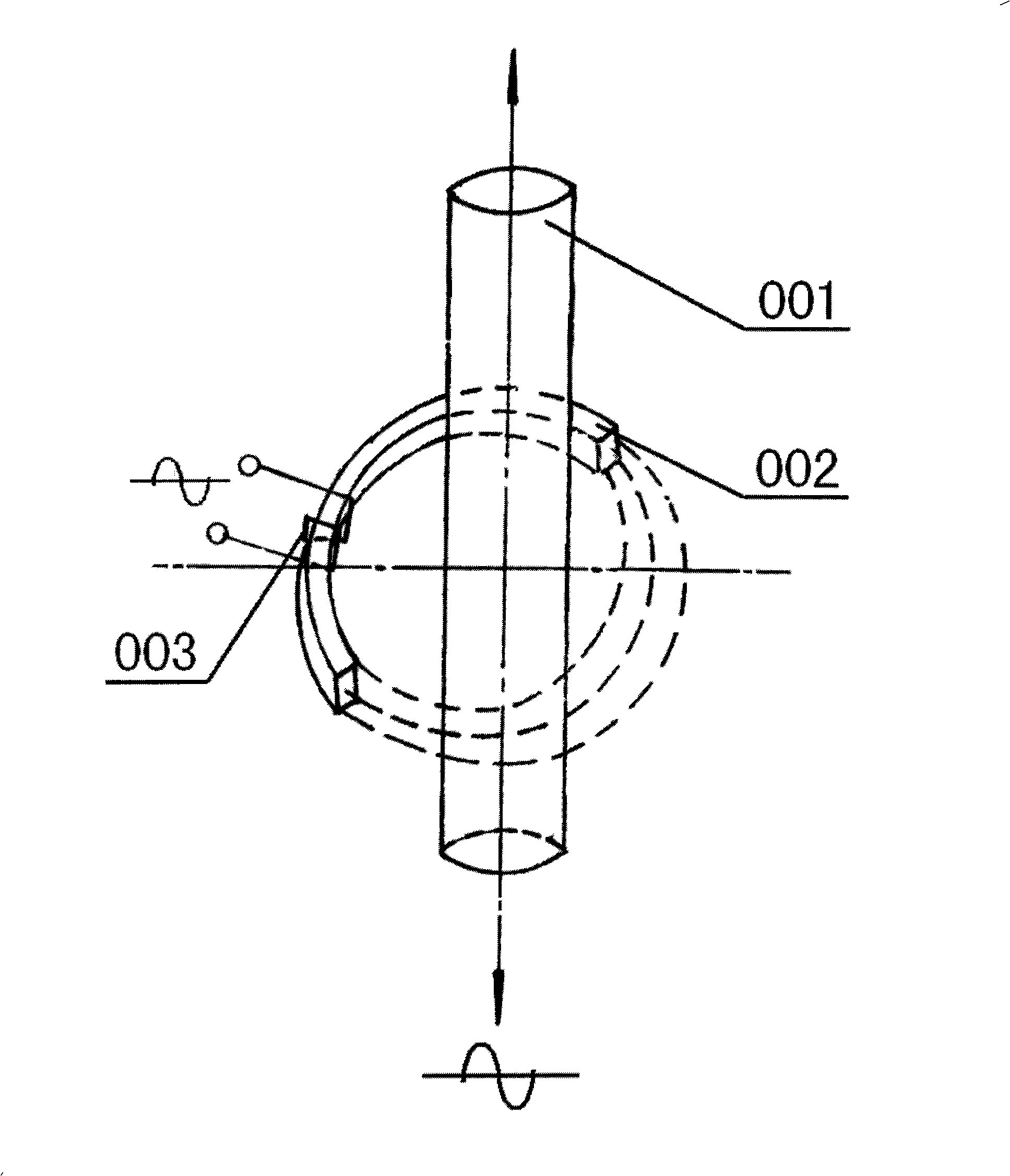
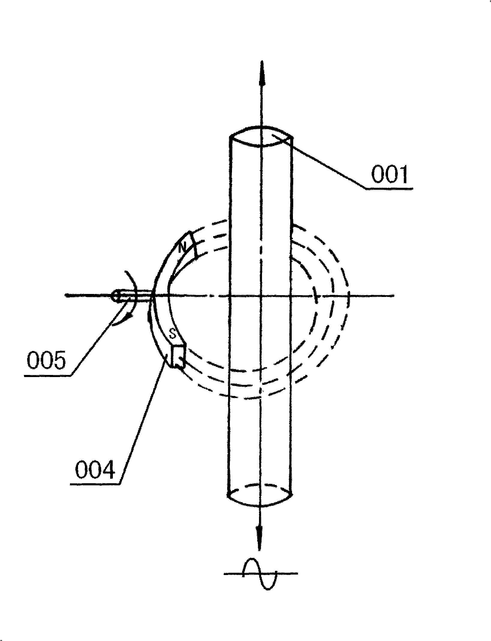
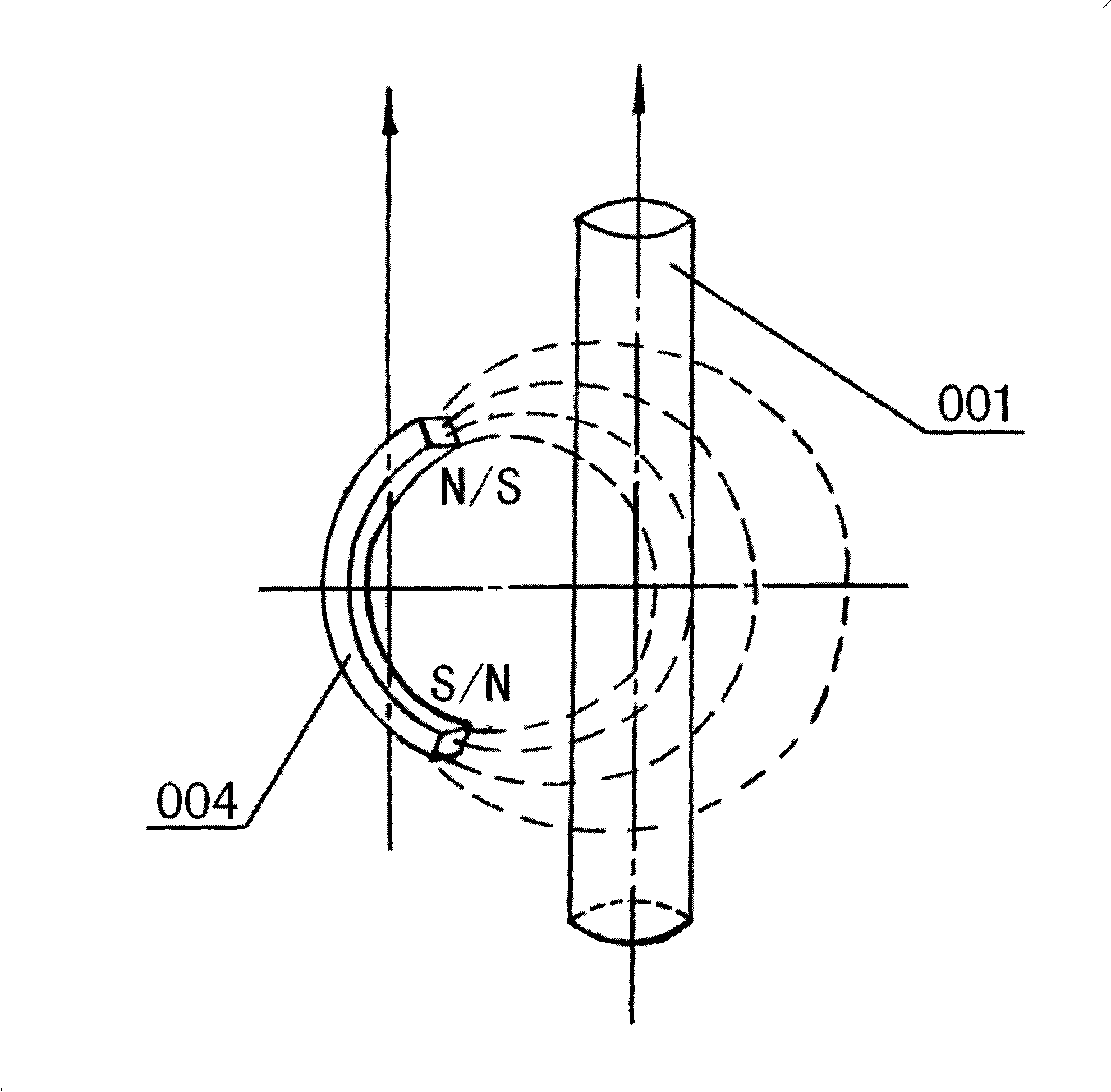
[0042] The simplest utility type such as Figure 6 shown. Figure 6 Among them, there are two C-type iron stator cores 101-1 and 101-2 on the upper and lower sides of the shaft 103, and at the counterparts of the two stator cores 101-1 and 101-2, there are two fixed The rotors 102-1 and 102-2 on the shaft have their own magnetic fields, which is called dual magnetic source type. There is a core iron 105 between the two rotors, which communicates with the magnetic circuit, and it is two ring magnet magnetic circuits corresponding to opposite directions, such as Figure 7 In the upper middle part, the magnetic poles of the two magnetic sources are opposite. It has two separate stator windings 104-1 and 104-2. Figure 7 yes Figure 6 side view.

[0043] The second embodiment is a three-phase alternating current motor, and it is still described with the generator earlier.

[0044] Figure 8 , Figure 9 A three-phas...


PUM


Abstract

The invention relates to a motor comprising a stator, a stator winding, a rotor, a rotor winding, a shaft and relative positioning parts. On the action principle the motor acts according to the change of magnetic field size and direction around the conductor and does not need a plurality of trunking structures on the stator, further all the sections of the winding conductor generates electromagnetic induction action, that is hundred-percent effective. Because the stator winding is independent to each other and the stacking and pressing between the multi-trunking and the multi-winding does not exist, not only the withstand voltage obstacle is overcome, but also solves the problem that joints exists between the multiple windings and the multiple circles, reduces many working procedures and cost and saves energy. The motor of the invention can be an ac motor, a dc motor and motors for special use.

Description

[0001] Technical scope: [0002] The invention belongs to motors. It is a generator, motor. In particular, its principle of action is based on: generators and motors that act on the change of the magnetic field around the wire. technical background: [0003] As a motor made of electromagnetic induction, the principle of the previous generator is: the wire cuts the magnetic force line to generate current, and when the wire moves perpendicular to the magnetic force line, the induced potential is the strongest; while the motor has a magnetic field in the magnetic field. When the wire passes through the current, the wire will move, and the force will be the largest when it is perpendicular to the magnetic force line. The direction of the current generated by the wire and the direction of movement can be judged by the right-hand and left-hand rules respectively. [0004] One problem is: as a generator, for the "wires" in the structure, there is a difference between an effective ...

Claims


Application Information

Patent Timeline
IPC IPC(8): H02K3/04
Inventor 徐文廷徐凌宇徐怀宇徐淑英唐文晶郭非凡苏坤祥
Owner 徐文廷
Learn More