Method and apparatus for manufacturing lens on LED apparatus

A technology of LED device and manufacturing method, which is applied to components of lighting devices, lighting devices, semiconductor devices of light-emitting elements, etc., can solve problems such as differences in refractive index and reduced light-gathering efficiency, and achieve cost reduction and light-gathering efficiency. Reduced effect

Inactive Publication Date: 2009-01-28
EVERLIGHT ELECTRONICS
View PDF0 Cites 2 Cited by
  • Summary
  • Abstract
  • Description
  • Claims
  • Application Information

AI Technical Summary

Problems solved by technology

[0007] Another object of the present invention is to provide a method for manufacturing a lens on an LED device and a mold device for making a lens on an LED device. The reusable mold is used to form the shape of the lens to reduce costs and solve problems caused by the existing The difference in refractive index between the lens and the encapsulant leads to a decrease in light collection efficiency

Method used


Image

  • Method and apparatus for manufacturing lens on LED apparatus
  • Method and apparatus for manufacturing lens on LED apparatus
  • Method and apparatus for manufacturing lens on LED apparatus

Examples


Embodiment Construction

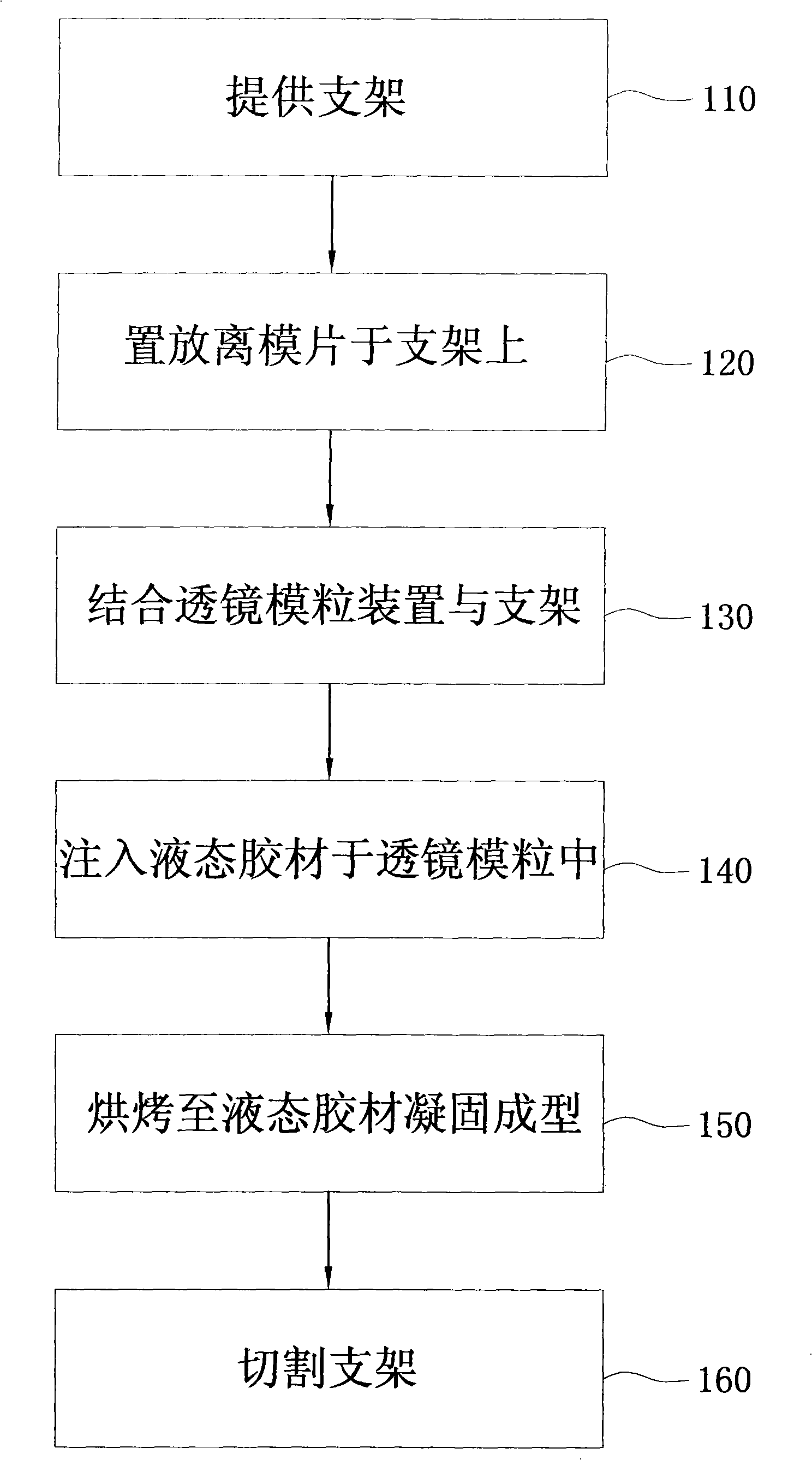
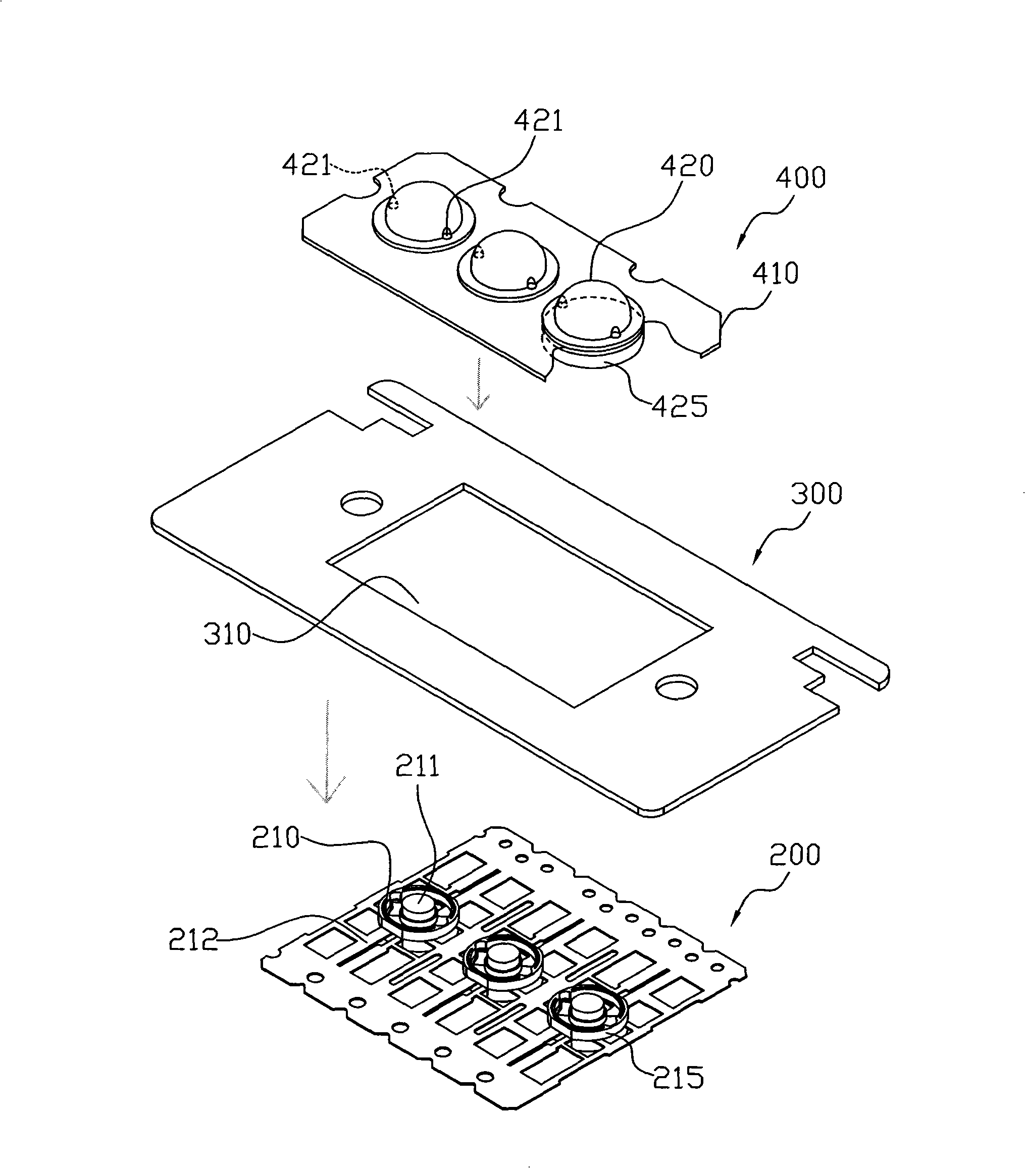
[0033] Please refer to figure 1 as well as figure 2 . figure 1 It is a flowchart of the lens manufacturing method of the present invention; figure 2 A three-dimensional exploded view showing the assembly structure in the lens manufacturing method of the present invention.

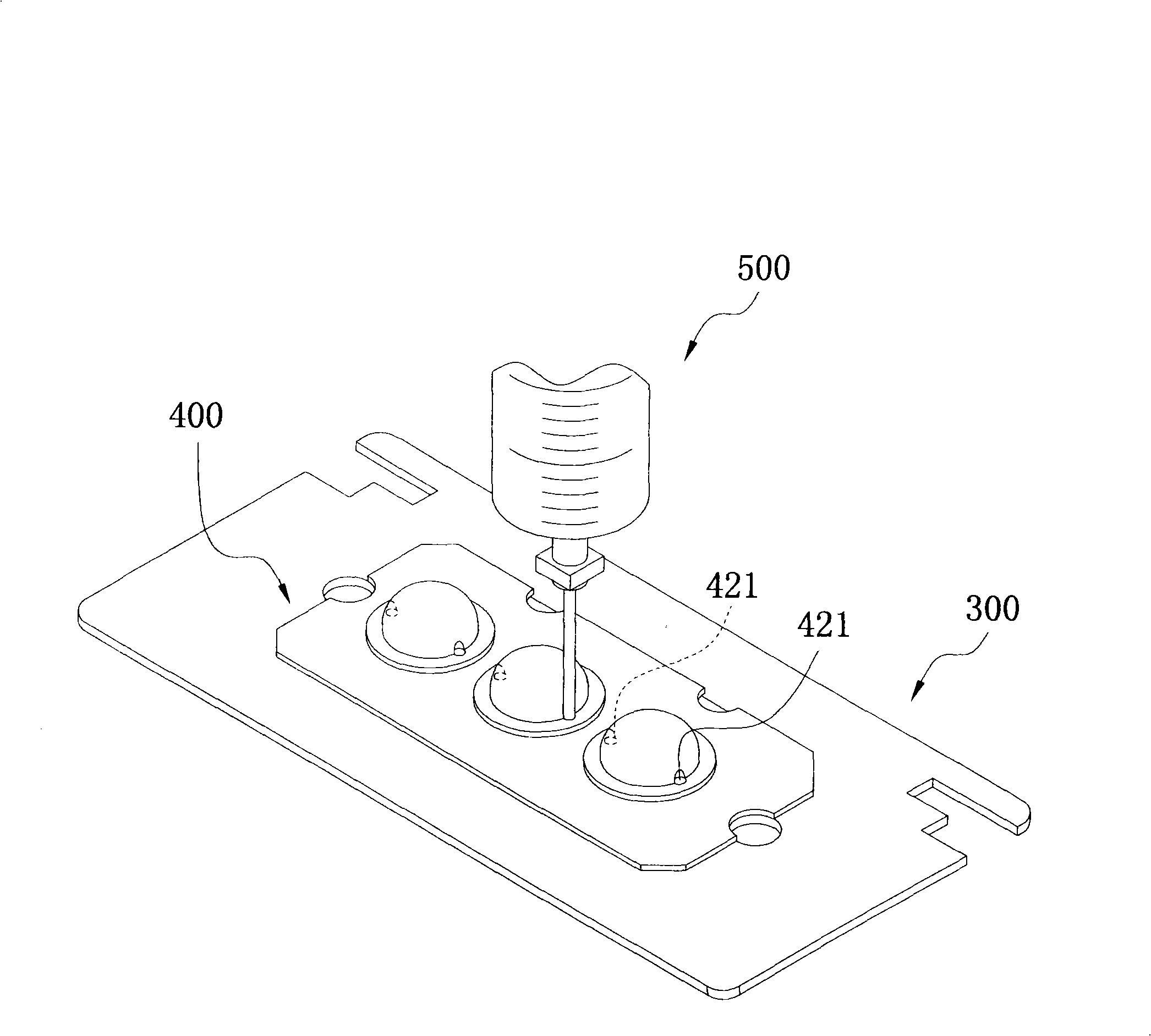
[0034] The lens manufacturing method of the present invention includes providing a bracket, placing a mold piece on the bracket, combining the lens module device with the bracket, injecting liquid glue, and baking and solidifying.

[0035] The bracket 200 includes a plurality of LED modules 210 , and each LED module 210 includes a die bonding area 211 and a lead frame 212 . The die-bonding area 211 is for the LED die to be fixed therein, and wires are connected from the LED die to the lead frame 212 through a wire bonding process (Wire Bonding) to drive the LED die to emit light. Each LED module 210 further includes a first combining portion 215 . The release sheet 300 includes a hollow area 310 corr...


PUM


Abstract

The invention discloses a method for manufacturing a lens on an LED device. The manufacturing method includes the following steps: a stand which includes a plurality of LED modules is provided; a module separating sheet which consists of a hollow area is placed on the stand and the hollow area ensures that the LED modules are exposed; a lens module particle device and the stand are combined, wherein, the lens module particle device comprises a plurality of lens module particles each of which even comprises two through holes and corresponds to each LED module on the stand; a liquid gum is injected by making use of one through hole of each lens module particle, followed by drying, solidifying and forming. The invention also provides a module particle device for making the lens on the LED device, which comprises a basic plate and a plurality of lens module particles installed on the basic plate and each lens module particle consists of two through holes used for injecting with the liquid gum. By adopting the invention, the steps of the process for forming the lens can be simplified and the time spent in the whole process can also be shortened; in addition, the cost can also be reduced due to the reusage of the lens module particle device.

Description

technical field [0001] The invention relates to a method for manufacturing a lens on an LED device, in particular to a method and a device for manufacturing a glue-injected lens by using a lens mold device. Background technique [0002] Light Emitting Diode (LED) has gradually replaced traditional lighting fixtures such as incandescent bulbs and halogen lamps due to its fast response, small size, low power consumption, low heat, and long service life. Therefore, from the beginning, LED was used as the status indicator of electronic devices, developed and applied to become the backlight of liquid crystal display, and then expanded to electronic lighting and even lighting in projectors. The application of LED is still continuing with the advancement of technology. in the extension. [0003] In the LED packaging process, in order to enhance the light-gathering effect, a lens (LENS) will be designed on the LED module. In the existing lens manufacturing method, a lens is covere...

Claims


Application Information

Patent Timeline
Patent Type & Authority Applications(China)
IPC IPC(8): F21V5/04F21V19/00H01L33/00F21Y101/02F21Y115/10H01L33/58
Inventor 林荣泉谢忠全
Owner EVERLIGHT ELECTRONICS
Why Eureka
Try Eureka