Temperature equalization plate and interlaced capillary structure and method for manufacturing the same

A capillary structure and manufacturing method technology, applied in heat exchange equipment, cooling/ventilation/heating transformation, electrical components, etc., can solve the problems of extended time required for liquid working fluid delivery, limited number of capillary paths, dry burning, etc.

Inactive Publication Date: 2009-01-28
贸晖科技股份有限公司
View PDF0 Cites 5 Cited by
  • Summary
  • Abstract
  • Description
  • Claims
  • Application Information

AI Technical Summary

Problems solved by technology

The corrugated plate form of the capillary structure (1a) can form a supporting effect on the one hand, and can form a return flow path of the liquid working fluid on the other hand, but because the capillary structure (1a) is essentially a sheet, in order to make it slightly deformable Because of its elasticity, its thickness is extremely limited, so the number of capillary paths that the capillary structure (1a) can produce is relatively limited, and its ability to transport liquid working fluid is insufficient. In addition, the capillary structure (1a) is in two The plate surface (2a, 3a) forms an oblique path whose length is longer than the vertical distance, and the time required for the liquid working fluid to be transported is relatively prolonged, making this vapor chamber very prone to dry-out. The working fluid has been completely vaporized, but the capillary structure (1a) cannot transport the liquid working fluid to the evaporation end in time

Method used


Image

  • Temperature equalization plate and interlaced capillary structure and method for manufacturing the same
  • Temperature equalization plate and interlaced capillary structure and method for manufacturing the same
  • Temperature equalization plate and interlaced capillary structure and method for manufacturing the same

Examples


Embodiment Construction

[0044] A preferred embodiment of the present invention will be described below with reference to the accompanying drawings. However, the relative terms such as "horizontal", "vertical" or "up and down" mentioned in the following descriptions are usually used in conjunction with the viewing angle or direction of the drawings for the convenience of explanation. Unless otherwise specified, they are not absolute or constant state.

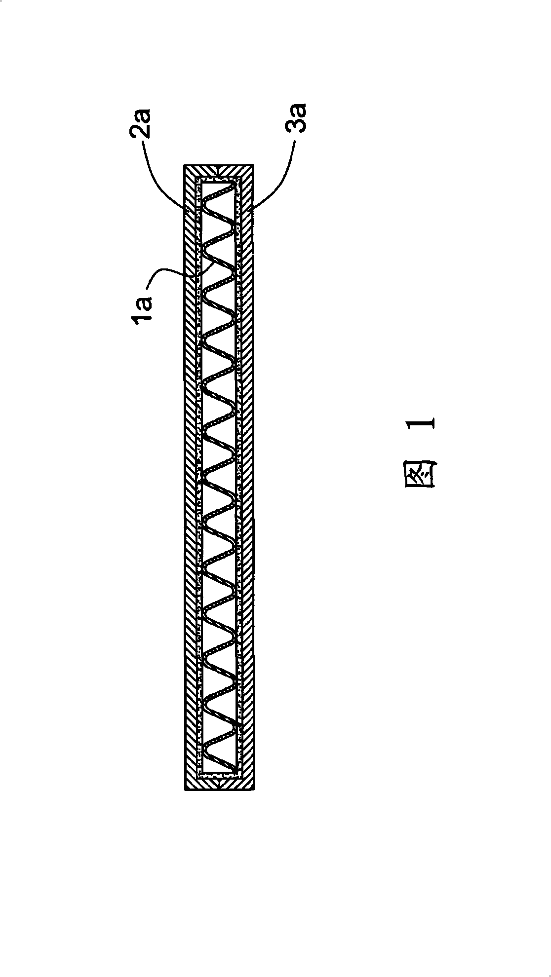
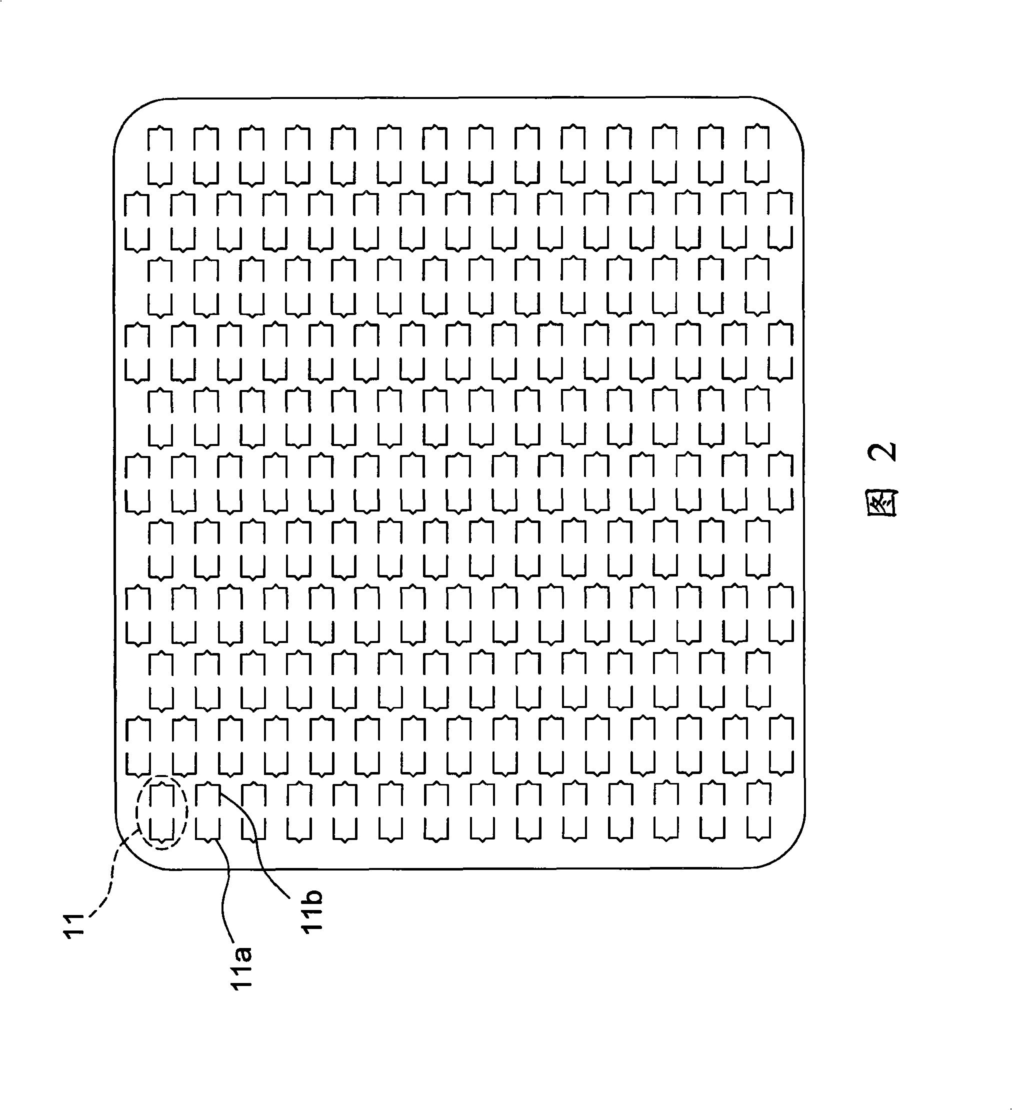
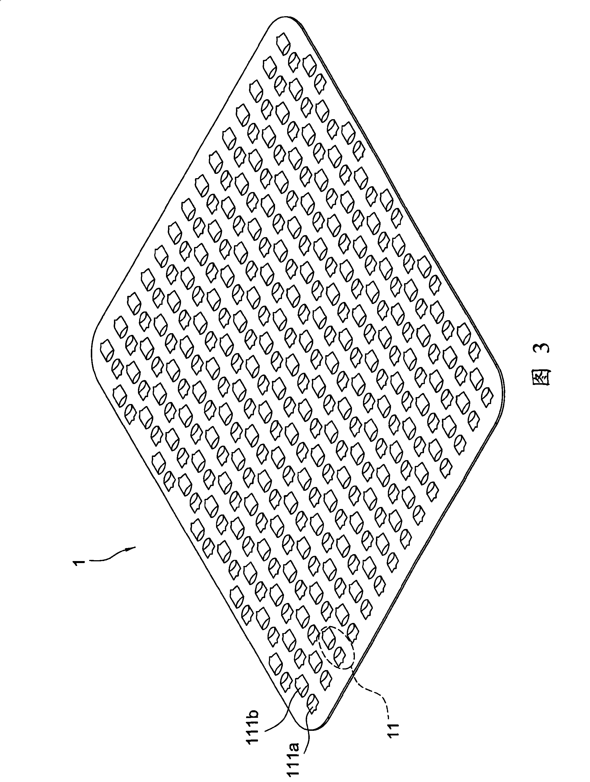
[0045] Fig. 2 is the front view of the first state of the sheet part of the present invention. First, a metal sheet 1 is provided, whose shape corresponds to the temperature chamber to be assembled. It is represented by a rectangle in the figure, and it can also be circular, triangular or other flat shapes. A plurality of pairs of {}-shaped grooves 11 are opened on the plate 1, and each group of grooves 11 is composed of two opposite unilateral grooves 11a, 11b, and their arrangement is in the form of a staggered matrix as shown in the figure It is t...


PUM


Abstract

The invention relates to a temperature equalizing plate and a staggered capillary structure thereof and a manufacturing method of the capillary structure. The manufacturing method of the invention mainly includes that: a plurality of groups of grooves with the shape of curly brackets in pairs are cut on a metal plate and then arrayed on the plate in a staggered manner; semi-cylindrical plate bodies are stamped towards different sides on a plate surface space surrounded by each single-side groove of each group of grooves; a porous layer is arranged on the plate surface of the plate and a cylindrical porous body is respectively fixed in each semi-cylindrical plate body; two porous bodies and the semi-cylindrical plate bodies in each group of grooves are reversely and vertically rotated so as to be vertical to the metal plate; finally, the plate and the porous bodies are placed in a shell body together so that two end faces of the porous bodies and the plate body can be respectively contacted with the plate surface of the shell body, namely a temperature equalizing plate is formed.

Description

technical field [0001] The invention relates to heat pipes, in particular to capillary structures of heat pipes. Background technique [0002] The principle of the heat pipe is to use the latent heat of the working fluid to generate heat transfer. Its structure is mainly to insert the working fluid and capillary structure in a closed tube body, and form a low pressure inside the tube. state. The pipe body can be divided into an evaporating part and a condensing part. The working fluid absorbs external heat in the evaporating part and evaporates into gas. Flow, the latent heat carried by the gaseous working fluid is absorbed by the radiator at the condensing end, so that the gaseous working fluid becomes liquid. The liquid phase working fluid is then drawn by the capillary pressure of the capillary structure to reflux to the evaporation end, and such a repeated cycle can achieve an excellent heat transfer effect. [0003] The principle of the vapor chamber is very similar ...

Claims


Application Information

Patent Timeline
Patent Type & Authority Applications(China)
IPC IPC(8): F28D15/04H05K7/20H01L23/34B21D53/02
Inventor 王子
Owner 贸晖科技股份有限公司
Why Eureka
Try Eureka