Direct foundry connection method for rare-earth permanent magnet motor rotor magnetism-isolating loop

A technology of rare earth permanent magnet motor and connection method, which is applied in the direction of magnetic circuit rotating parts, manufacturing stator/rotor body, magnetic circuit shape/style/structure, etc., and can solve problems such as unfavorable mass production and time-consuming processing

Inactive Publication Date: 2009-01-28
林增禄 +1
View PDF0 Cites 2 Cited by
  • Summary
  • Abstract
  • Description
  • Claims
  • Application Information

AI Technical Summary

Problems solved by technology

[0003] The purpose of the present invention is to provide a direct casting and connecting method of the magnetic isolation ring of the rare earth permanent magnet motor rotor, so as to overcome the defects of time-consuming processing and unfavorable mass production in the prior art

Method used


Image

  • Direct foundry connection method for rare-earth permanent magnet motor rotor magnetism-isolating loop
  • Direct foundry connection method for rare-earth permanent magnet motor rotor magnetism-isolating loop

Examples


specific Embodiment approach 1

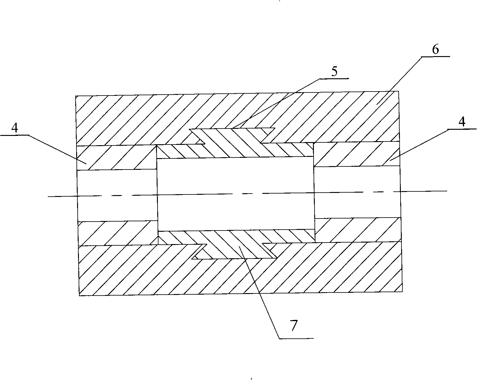
[0005] Specific implementation mode one: the following combination figure 2 This embodiment will be specifically described. This embodiment is realized by the following steps: 1. Process two magnetic isolation ring bodies 4 by turning; 2. Set the two magnetic isolation ring bodies 4 on the two ends of the inner hole of the rotor body 6 respectively; 1. Pouring the molten stainless steel into the space formed by the two magnetic isolation ring bodies 4 and the inner wall of the rotor body 6, so as to solidify into a stainless steel magnetic isolation sleeve 7, and the stainless steel magnetic isolation sleeve 7 is connected with the magnetic isolation ring body 4 respectively. The inner end surface and the inner wall of the rotor body 6 are condensed into one body. The material of the magnetic isolation ring body 4 and the stainless steel magnetic isolation sleeve 7 is 1Cr18Ni9Ti. The advantage of this arrangement is that the same metal is easy to connect.

specific Embodiment approach 2

[0006] Specific implementation mode two: the following combination figure 2 This embodiment will be specifically described. The difference between this embodiment and Embodiment 1 is that: a dovetail ring groove 5 is processed on the inner wall at the middle section of the inner hole of the rotor body 6 . With such arrangement, the molten stainless steel flows into and solidifies in the dovetail ring groove 5 , which can improve the connection strength between the stainless steel magnetic isolation sleeve 7 and the inner wall of the rotor body 6 .


PUM


Abstract

The invention discloses a direct casting connection method for magnetic isolation rings of a rotor of a rare earth permanent-magnet motor and relates to an assembly method for the magnetic isolation rings of the rotor of the rare earth permanent-magnet motor. The method overcomes the defects that the prior technology has time-consuming processing and does not contribute to the mass production. The method is realized through the following steps: firstly, a turning method is used to process two magnetic isolation ring bodies (4); secondly, the two magnetic isolation ring bodies (4) are respectively arranged on both ends of an inner hole of a rotor block (6); and thirdly, molten stainless steel is cast into a space formed between the two magnetic isolation ring bodies (4) and the inner wall of the rotor block (6), thereby solidifying into a stainless steel magnetic shield (7), and the stainless steel magnetic shield (7) is respectively solidified into a whole with the inner end surfaces of the magnetic isolation ring bodies (4) and the inner wall of the rotor block (6). The method can finish the work of shaping the magnetic shield and fixing the magnetic isolation rings in the inner hole of the rotor (6) by casting one time, and overcomes the defect that the magnetic isolation rings in the prior technology need to be welded and fixed for a few times.

Description

technical field [0001] The invention relates to an assembly method of a magnetic isolation ring of a rare earth permanent magnet motor rotor. Background technique [0002] The new energy-saving rare earth permanent magnet motor rotor is cast from low carbon steel. The inner hole of the rotor needs a magnetic isolation ring to isolate the magnetic circuit between the rotor and the rotor shaft. The assembly process of the magnetic isolation ring of the existing rare earth permanent magnet motor rotor is as follows: figure 1 As shown, the inner hole of the rotor 1 and the three magnetic isolation rings 2 are turned to the specified size first, and then the three magnetic isolation rings 2 are uniformly arranged in the inner hole of the rotor 1 and fixed by welding with an austenitic welding rod. This process requires many man-hours for mechanical processing, and also requires welding rod costs, welding costs and welding man-hours, so it is not conducive to mass production. ...

Claims


Application Information

Patent Timeline
Patent Type & Authority Applications(China)
IPC IPC(8): H02K15/03H02K1/27
Inventor 林增禄
Owner 林增禄
Why Eureka
Try Eureka