Five-axle linked blade processing center

A machining center, five-axis linkage technology, applied in metal processing equipment, metal processing mechanical parts, driving devices, etc., can solve the problems of large relative positional error, unsatisfactory blade accuracy, poor control accuracy of tool compensation, etc. Accuracy improvement, error reduction, reasonable operation effect

Inactive Publication Date: 2009-02-04
JIANGSU SHINRI HEAVY IND SCI & TECH
View PDF0 Cites 12 Cited by
  • Summary
  • Abstract
  • Description
  • Claims
  • Application Information

AI Technical Summary

Problems solved by technology

[0003] The main structure of the existing five-axis linkage blade machining center includes a bed, a carriage for X-axis movement, a column for Y-axis movement, a turntable for A-axis movement, a Z-axis slide plate, and a headstock for B-axis movement. The box is installed on the Z-axis slide plate, but this five-axis linkage machining center has the following defects: First, because the tool is far away from the rotary center, the programming is quite complicated and lengthy, and the control accuracy of the tool compensation is also poor; The second is that the relative positional relationship between the tool and the workpiece is offset, resulting in a large error, and the precision of the processed blades cannot meet the existing needs.

Method used


Image

  • Five-axle linked blade processing center
  • Five-axle linked blade processing center
  • Five-axle linked blade processing center

Examples


Embodiment Construction

[0014] The specific embodiment of the present invention will be further described in detail below in conjunction with the accompanying drawings.

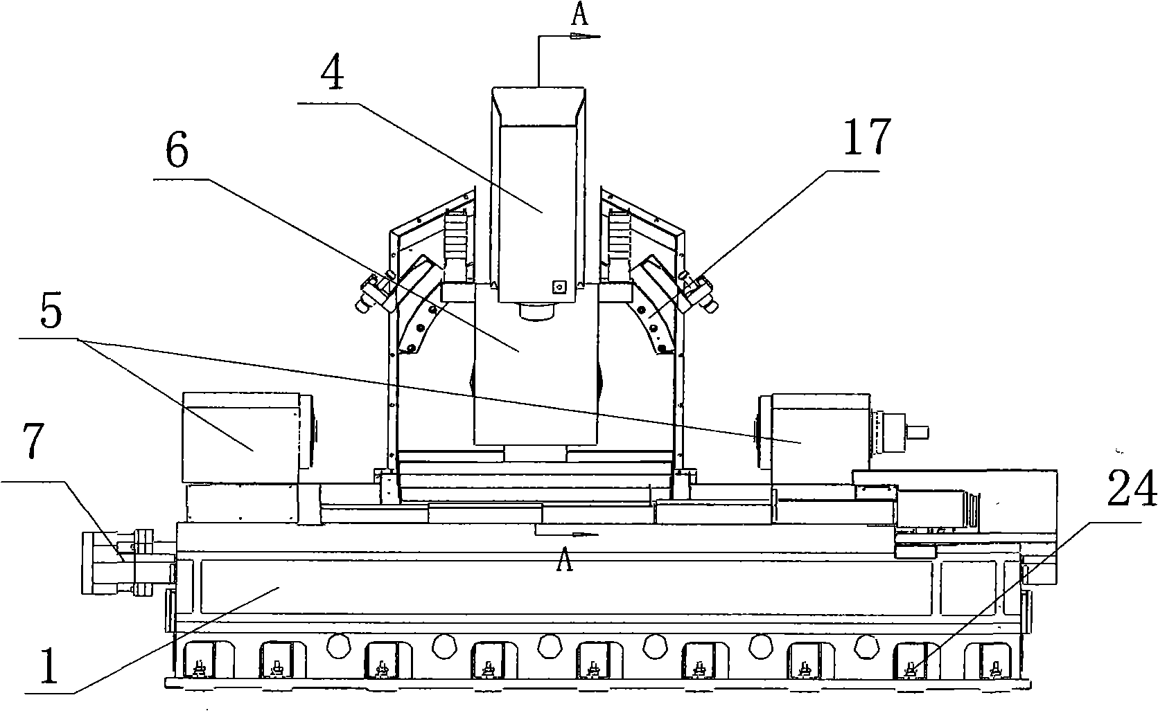
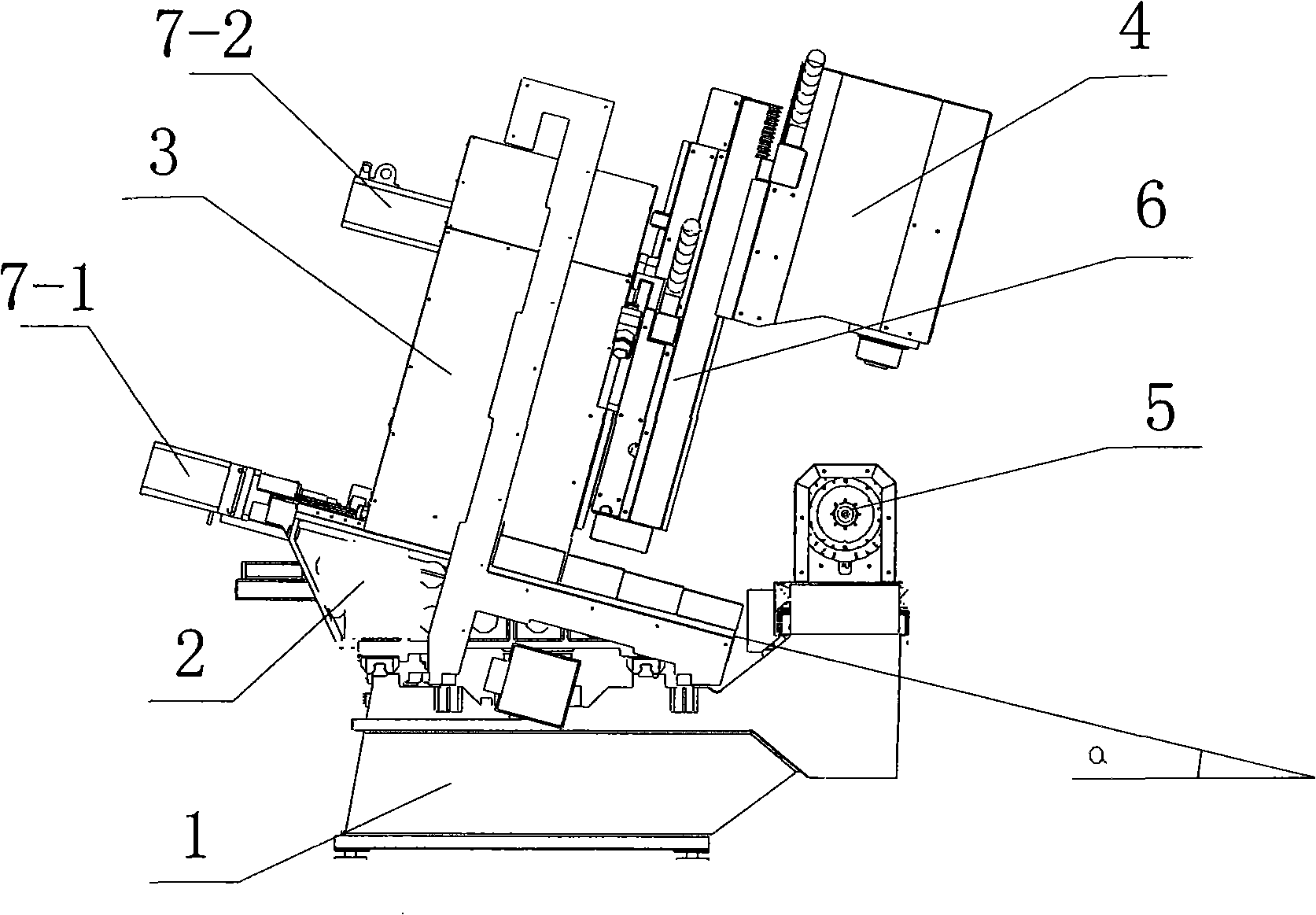
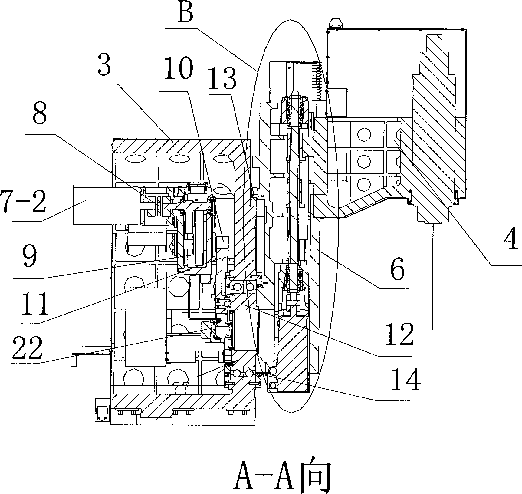
[0015] figure 1 with figure 2 It is two plan views of a preferred embodiment of the five-axis linkage blade machining center of the present invention. refer to figure 1 with figure 2 , the five-axis linkage blade machining center includes a bed 1, a turntable 5 installed on the bed 1, a carriage 2 that can move along the bed 1, a column 3 that can move along the carriage 2, a swing mechanism and a headstock 4, The swing mechanism comprises a pendulum shaft 6 and a pendulum shaft drive mechanism, the pendulum shaft 6 is installed on the column 3, the pendulum shaft drive mechanism is placed in the column 3, and the column 3 is provided with an arc track 17 for the pendulum shaft 6 to swing, and the pendulum shaft 6 is provided with a feed mechanism for moving the spindle box 4, and the spindle box 4 is installed on the swing sh...


PUM


Abstract

The invention discloses a center for processing a five-shaft linkage blade, which comprises a lathe bed, a rotary table installed on the lathe bed, a trailing bar which can move along the lathe bed, a column which can move along the trailing bar, a swinging mechanism and a main shaft case, wherein, the swinging mechanism comprises a swinging shaft and a swing shaft drive mechanism; the swinging shaft is installed on the column and the swinging shaft drive mechanism is positioned in the column; an arc-shaped railway is arranged on the column by which the swinging shaft can swing; a feed mechanism for moving the main shaft case is arranged in the swinging shaft; the main shaft case is installed on the swinging shaft and can move along the swinging shaft. Due to the mechanical transmission structure, the errors caused by the drifting of mechanical structure self are reduced, thus the transmission of the system and the operation of a cutting-tool and a workpiece are more reasonable and harmonious; the distance between the cutting tool and the processing surface is shortened to a fullest extend; and the errors are reduced; in addition, the control of the problems such as tool compensation amount and the programming of the entire structure are more direct and compact, thus enhancing work efficiency and finally enhancing the precision for processing the workpiece.

Description

technical field [0001] The invention relates to a numerical control machine tool, in particular to a five-axis linkage blade machining center. Background technique [0002] Multi-axis linkage CNC machining is the most difficult but most widely used technology in CNC technology. It is mainly used for efficient, precise and automatic processing of complex curved surfaces. It is the key processing equipment for important civil and military industries such as power generation, ships, and aerospace. Internationally, multi-axis linkage CNC machining technology is used as a symbol of a country's industrialization level. The five-axis linkage machining center is a CNC machine tool composed of linear coordinate axes (X, Y, Z) and two rotary coordinate axes (A, B) to realize five-axis linkage interpolation machining. Among them, the five-axis linkage blade machining center is specially used to process various blades of steam turbines and aircraft engines and other narrow and long par...

Claims


Application Information

Patent Timeline
Patent Type & Authority Applications(China)
IPC IPC(8): B23Q1/01B23Q1/25B23Q5/10B23Q5/32B23Q17/00
Inventor 周立群洪宁马励徐志华刘伯军苏丽华朱蕾
Owner JIANGSU SHINRI HEAVY IND SCI & TECH
Why Eureka
Try Eureka