Two-dimensional groove directed microstrip paster antenna

A microstrip patch antenna and groove technology, which is applied to antennas, electrical components, etc., can solve the problems of reducing the front-to-back ratio of the radiation energy of the antenna, serious surface wave diffraction at the edge of the metal plate, and enhanced backward radiation of the antenna. Improve front-to-back ratio, high directivity, and reduce the effect of backward radiation

Inactive Publication Date: 2009-02-04
INST OF OPTICS & ELECTRONICS - CHINESE ACAD OF SCI
View PDF0 Cites 9 Cited by
  • Summary
  • Abstract
  • Description
  • Claims
  • Application Information

AI Technical Summary

Problems solved by technology

Based on this theory, M.Bertete et al. designed a new type of low-profile slot feed antenna by using the "bull's eye" groove structure, which can greatly improve the gain of the antenna. The radiation is more serious, which leads to the enhancement of the backward radiation of the antenna and reduces the front-to-back ratio of the antenna radiation energy.

Method used


Image

  • Two-dimensional groove directed microstrip paster antenna
  • Two-dimensional groove directed microstrip paster antenna
  • Two-dimensional groove directed microstrip paster antenna

Examples


Embodiment Construction

[0031] The present invention will be described in detail below in conjunction with the accompanying drawings and specific embodiments, but the scope of protection of the present invention is not limited to the following examples, but should include all content in the claims. Moreover, those skilled in the art can realize all the content in the claims from the following embodiment.

[0032] The concrete process of the embodiment of the present invention is as follows:

[0033] (1) The operating frequency of the microstrip patch antenna is selected as 12.8GHz, and its wavelength can be obtained as 23.4mm;

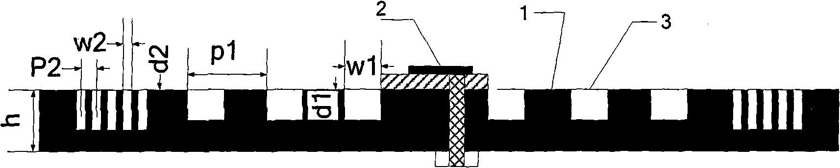
[0034] (2) The metal plate material is selected as aluminum, its shape is square, and its thickness h is 7mm;

[0035] (3) Place a 6.6 x 6.6mm square in the center of the metal plate surface. 2 The microstrip patch antenna is used as the radiation source, and the dielectric substrate between the metal plate and the antenna is Rogers 5880 (dielectric constant is 2.2, the rad...


PUM


Abstract

Disclosed is a two-dimensional trench-oriented micro-strip patch antenna, which is characterized in that: firstly, the operating frequency f of the patch antenna is established; secondly, the metal plate material is selected and the thickness of the metal plate is h; thirdly, a micro-strip patch antenna is arranged in the central region of the metal plate and is fed with electricity by making use of the coaxial line; fourthly, N1 ring-shaped trenches are cyclically arrayed and distributed on the exit surface of the metal plate with a cycle of P1, a depth of d1 and a width of w1; finally, N2 traditional ring-shaped trenches are cyclically arrayed and distributed outside the trenches with a cycle of P2, a depth of d2 and a width of w2, and the manufacturing is finished; and the invention adopts a theory that the trench structure modulates the surface wave in order to improve the antenna radiation performance and a theory that the traditional trench structure inhibits the metal plate edge surface wave in order to reduce backward radiation, both of which are integrated and used in the micro-strip patch antenna, so as to improve the front to back ratio of antenna radiation energy and obtain significantly enhanced radiation gains, and meanwhile the antenna beam width can be substantially compressed.

Description

technical field [0001] The invention relates to a design method of a microstrip patch antenna with high radiation performance, in particular to a two-dimensional groove directional microstrip patch antenna. Background technique [0002] Microstrip patch antennas have great development prospects in military and civilian fields due to their low cost, light weight, and low profile. However, this type of antenna also has some disadvantages, such as the loss of surface waves, the radiation efficiency of the antenna Very low, and the frequency bandwidth is extremely narrow, which limits its development. How to reduce the loss of surface waves and improve the radiation performance of patch antennas has become a key direction in the field of antenna research. There are two commonly used methods: one is the artificial electromagnetic wave soft surface, that is, the traditional periodic groove structure, on the soft surface The electric field strength of any polarization is zero, tha...

Claims


Application Information

Patent Timeline
Patent Type & Authority Applications(China)
IPC IPC(8): H01Q13/08H01Q3/00
Inventor 黄成崔建华罗先刚赵泽宇
Owner INST OF OPTICS & ELECTRONICS - CHINESE ACAD OF SCI
Why Eureka
Try Eureka