Pulse width modulation method based on minimum common mode transient voltage superimposed

A technology of common-mode voltage and pulse width modulation, applied in the direction of AC motor control, electrical components, control systems, etc., can solve problems such as large common-mode voltage, inability to directly obtain modulation signals, and increased complexity

Active Publication Date: 2009-02-04
TSINGHUA UNIV
View PDF3 Cites 11 Cited by
  • Summary
  • Abstract
  • Description
  • Claims
  • Application Information

AI Technical Summary

Problems solved by technology

But this method also has some defects: firstly, the common-mode voltage is too large, which is easy to cause loss and electromagnetic compatibility problems, especially in some high-voltage applications; secondly, the concept of space vector is abstract, and the modulation signal cannot be directly obtained, and the calculation process is cumbersome , the steps of coordinate transformation, sector judgment and trigonometric function operation are required
The above

Method used


Image

  • Pulse width modulation method based on minimum common mode transient voltage superimposed
  • Pulse width modulation method based on minimum common mode transient voltage superimposed
  • Pulse width modulation method based on minimum common mode transient voltage superimposed

Examples


Embodiment Construction

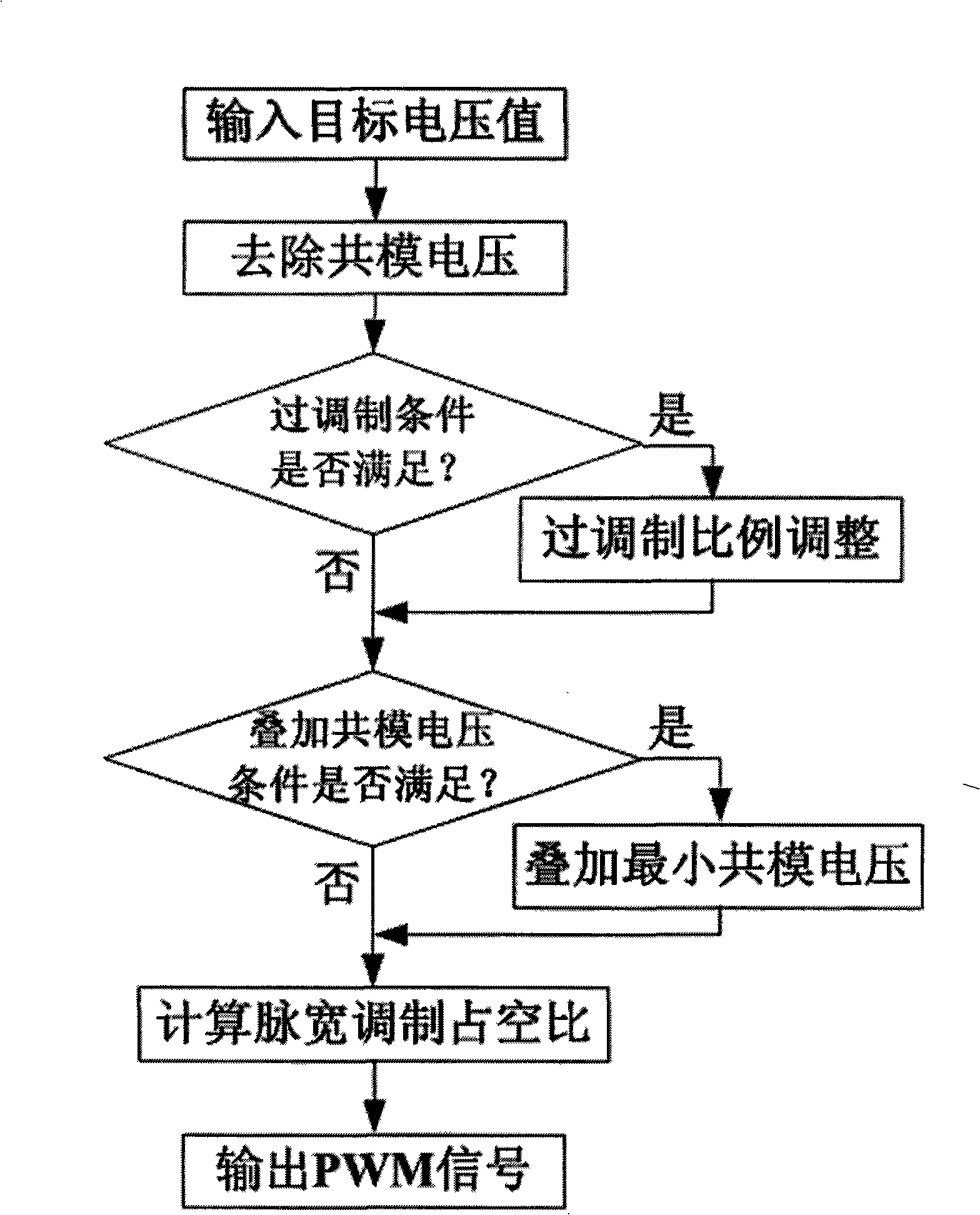
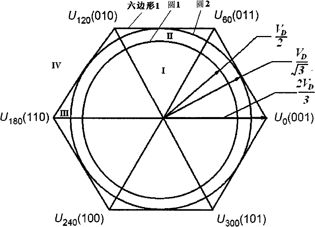
[0063] The present invention proposes a new type of pulse width modulation method, which is characterized in that the method can give the power unit by directly analyzing and calculating the target voltage value of each phase according to the limit condition of the output voltage state of the voltage source inverter device. control signal. The following takes a typical three-phase inverter system as an example to illustrate its working principle. as attached Figure 4 In the three-phase inverter circuit shown, the DC bus voltage is V D , select the DC bus voltage of As the reference voltage zero point, the attached Figure 4 Midpoint O. Using pulse width modulation methods such as SPWM or SVPWM to control the power switch T 1 ~T 6 Modulation control can output controlled AC voltage at A, B, and C terminals.

[0064] The present invention directly provides the target value of each phase voltage according to the physical limitation of the output state of the inverter dev...


PUM


Abstract

The invention relates to a pulse width modulation method based on instantaneous minimum common-mode voltage superposition which belongs to the pulse width modulation control technical field of the power electronic transforming device. The method is characterized in that when an integrated circuit inputs a target voltage value of an instantaneous value form or a vector form, after coordinate conversion and the treatment of common-mode voltage removal, whether line voltage falls into the range from -VD to +VD is firstly taken as the condition to carry out an overmodulation judgment according to the output limit of an inversion device, wherein, VD is direct current bus voltage; if entering an overmodulation zone, phase-voltage target values are reduced with equal ratio to cause the line voltage to fall into the range from -VD to +VD; the obtained phase-voltage target values are both superposed with a minimum common-mode voltage falling into the range from -VD to +VD; then, each phase-voltage pulse width modulation duty cycle can be calculated. Compared with a space vector modulation method which is usually used at present, the method can cause the common-mode voltage to be reduced to the maximum extent to reach the minimum which can be reached by the method of the category in theory, and has simple calculation process.

Description

technical field [0001] The invention belongs to the technical field of pulse width modulation control of power electronic conversion devices, and can be applied to the control of AC motor speed regulation systems, AC power supplies, high-voltage and large-capacity power electronic conversion devices and other equipment. Background technique [0002] The pulse width modulation method is the core technology for controlling power electronic conversion devices at present. The earliest sine wave pulse width modulation method (SPWM) directly compares the sine command signal with the high-frequency carrier, and outputs the pulse width modulation signal, which is more suitable for realization by analog devices, so it is widely used in the past analog control systems. However, the output AC voltage of this method is low under a certain DC bus voltage, that is, the voltage utilization rate of the DC bus is low. For example, in a three-phase system, under the premise of ensuring that t...

Claims


Application Information

Patent Timeline
IPC IPC(8): H02M7/48H02M7/5387H02P27/08
Inventor 肖曦
Owner TSINGHUA UNIV
Why Eureka
Try Eureka