Surface illuminator and liquid crystal display using same

一种液晶显示装置、照明装置的技术,应用在面状照明装置,液晶显示装置领域,能够解决亮度小、没有启示和公开、显示面亮度不均等问题

Inactive Publication Date: 2009-02-04
PANASONIC CORP
View PDF4 Cites 13 Cited by
  • Summary
  • Abstract
  • Description
  • Claims
  • Application Information

AI Technical Summary

Problems solved by technology

[0014] Furthermore, in the example of Patent Document 3, the use of a red semiconductor laser is described as a specific example, but even in this example, there is no description at all of a specific method for obtaining uniform planar illumination light using a laser.
[0015] In addition, in the example of Patent Document 4, the occurrence of speckle noise is prevented by reciprocating the integrator lens, but the disclosed structure cannot be used as an illumination device for a backlight of a liquid crystal display device.
In addition, in this method, for the three-color laser light source using R light, G light and B light, there is no suggestion or disclosure
[0016] In addition, in conventional large-screen liquid crystal displays, the luminance of each light source element of the light source is small, so in order to obtain sufficient luminance, it is necessary to use multiple light sources in parallel.
In the case of using multiple light sources, there is a problem that unevenness in brightness occurs on the display surface because the initial unevenness in brightness and the change in characteristics due to changes over time are different from each other.

Method used


Image

  • Surface illuminator and liquid crystal display using same
  • Surface illuminator and liquid crystal display using same
  • Surface illuminator and liquid crystal display using same

Examples


no. 1 approach

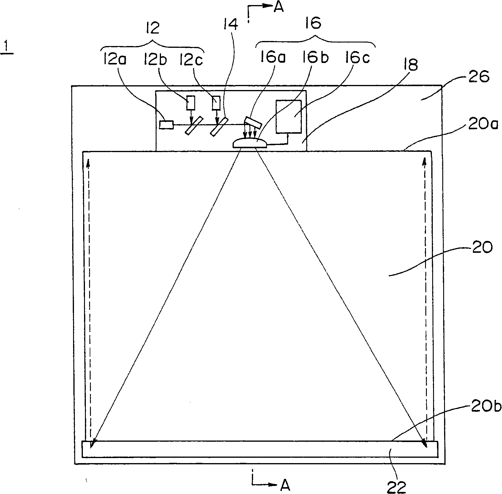
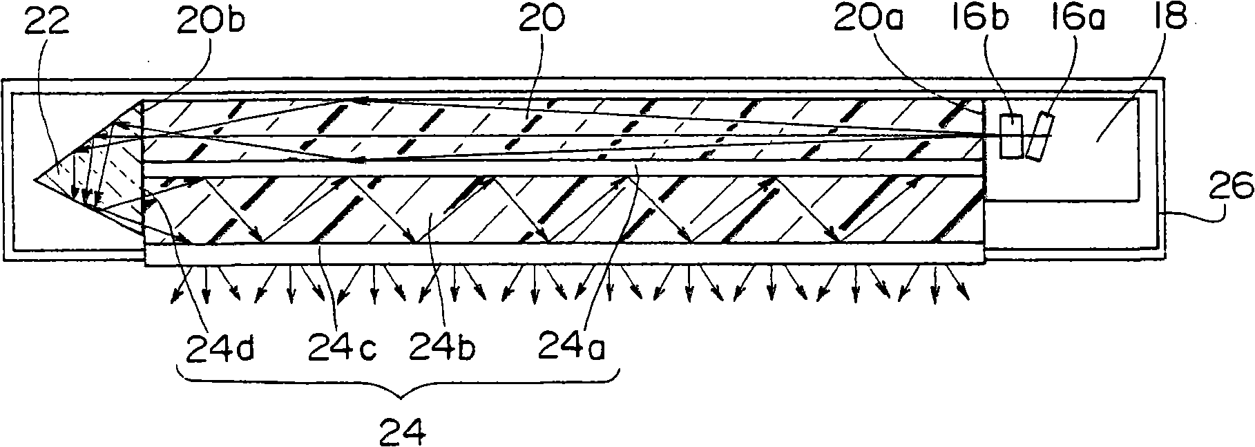
[0109] Figure 1A and Figure 1B It is a figure which shows the planar illuminating device which concerns on 1st Embodiment of this invention. Figure 1A It is a plan view showing the outline of the structure, Figure 1B is along Figure 1A A schematic diagram of the section cut along the A-A line of .

[0110] Such as Figure 1AAs shown, the planar lighting device 1 of the first embodiment is constituted by the following configuration. The planar light source device 1 has laser light sources 12a, 12b, and 12c. The laser light source 12 has three light sources that emit light of three primary colors of a red light (R light) source 12a, a green light (G light) source 12b, and a blue light (B light) source 12c.

[0111] In addition, refer to Figure 1B The planar lighting device 1 includes a first flat plate-shaped light guide plate (first light guide path) 24 that enters the laser beams emitted from the laser light sources 12a to c from one end surface portion 24d and emits ...

no. 2 approach

[0136] Figure 4A and Figure 4B It is a figure which shows the planar illuminating device 2 which concerns on 2nd Embodiment of this invention. Figure 4A It is a plan view showing the outline of the structure, Figure 4B is along Figure 4A A schematic diagram of a section taken along line B-B of .

[0137]The structure of the first light guide plate 36 of the planar lighting device 2 of the first embodiment is different from that of the first light guide plate 24 of the planar lighting device 1 of the first embodiment. That is, in the second embodiment, the first light guide plate 36 has a plurality of half mirrors 36 a arranged therein at a constant pitch. These half mirrors 36 a reflect a part of the laser light incident on the first light guide plate 36 in the direction of one main surface of the first light guide plate 36 (which includes the diffusion plate 36 ). Further, the half mirror 36 a varies the reflectance of the half mirror 36 a at a set ratio along the l...

no. 3 approach

[0140] Figure 5 It is a schematic plan view showing the structure of the planar lighting device 3 according to the third embodiment of the present invention. In the case of the planar lighting device 3 shown in the figure, the surfaces of the frame body 26 and the housing portion 16 are respectively removed, and the internal structure is shown in an easy-to-understand manner.

[0141] The beam scanning unit 38 of the planar illuminating device 3 according to the third embodiment is different in configuration from the beam scanning unit 16 of the first embodiment. That is, the cylindrical lens 16b is used in the beam scanning unit 16 of the planar lighting device 1 of the first embodiment, but the lenticular lens 38b is used instead of the cylindrical lens 16b in the planar lighting device 3 of the third embodiment. . The laser light is reflected by the reflection mirror 38a of the beam scanning unit 38, and enters the lenticular lens 38b. The laser beam incident on the len...


PUM


Abstract

A surface illuminator which uses a laser light source, has a uniform luminance over a large area and a wide color reproduction range, and produces suppressible speckle noise and a liquid crystal display using the illuminator are provided. The surface illuminator comprises a laser light source emitting a laser beam, a beam scan section for deflecting the laser beam for scanning, and a first plate-shaped light guide which receives the laser beam deflected for scanning by the beam scan scanning section at an end surface and outputs the laser beam from a first major surface. The liquid crystal display includes a liquid crystal display panel and the surface illuminator which serves as a backlight illuminator for illuminating the back of the liquid crystal display panel in the liquid crystal display.

Description

technical field [0001] The present invention relates to a planar lighting device using laser light as a light source and a liquid crystal display device using the same. Background technique [0002] Conventionally, in a liquid crystal display device using a liquid crystal display panel, a planar lighting device using a cold cathode fluorescent tube as a light source has been widely used as backlight illumination. The cold-cathode fluorescent tubes used therein utilize light emission of phosphors, and the range of color reproduction that can be displayed is limited. Therefore, various studies have been conducted to reproduce more vivid and natural color tones. Among them, a planar lighting device for a backlight using three-color light-emitting diodes (LED elements) of red light (R light), green light (G light), and blue light (B light) has attracted attention. A light source using LED elements of three or more colors of R light, G light, and B light has a wider color repro...

Claims


Application Information

Patent Timeline
Patent Type & Authority Applications(China)
IPC IPC(8): F21V8/00G02F1/133G02B6/00G02F1/13357G02B26/10F21Y101/02G02F1/1335
CPCG02F1/133621G02B27/1086G02B19/0057G02B19/0028G02B5/02G02B27/145G02B6/0066G02B27/106G02B27/144G02B27/1053G02B6/0028G02B26/105G02B27/48G02B3/0056
Inventor 水岛哲郎笠澄研一水内公典山本和久门胁慎一伊藤达男
Owner PANASONIC CORP
Why Eureka
Try Eureka