Liquid light hydrocarbon bump formatting carburettor

A vaporizer and bubbling technology, applied in the direction of liquid fuel supply/distribution, combustion methods, etc., can solve the problems of high manufacturing cost and complex structure, and achieve the effect of reducing equipment manufacturing cost and simple structure

Inactive Publication Date: 2009-02-11
张路
View PDF1 Cites 7 Cited by
  • Summary
  • Abstract
  • Description
  • Claims
  • Application Information

AI Technical Summary

Problems solved by technology

[0002] The bubbling carburetor is one of the main equipment in the light hydrocarbon mixed gas supply system. The Chinese patent authorization announcement number is CN2475945Y. The date of the authorization announcement is February 6, 2002. The name of the utility model is: stable light hydrocarbon vaporizer. In the authorization announcement Disclosed is a stable light hydrocarbon vaporizer. The

Method used


Image

  • Liquid light hydrocarbon bump formatting carburettor
  • Liquid light hydrocarbon bump formatting carburettor
  • Liquid light hydrocarbon bump formatting carburettor

Examples


Example Embodiment

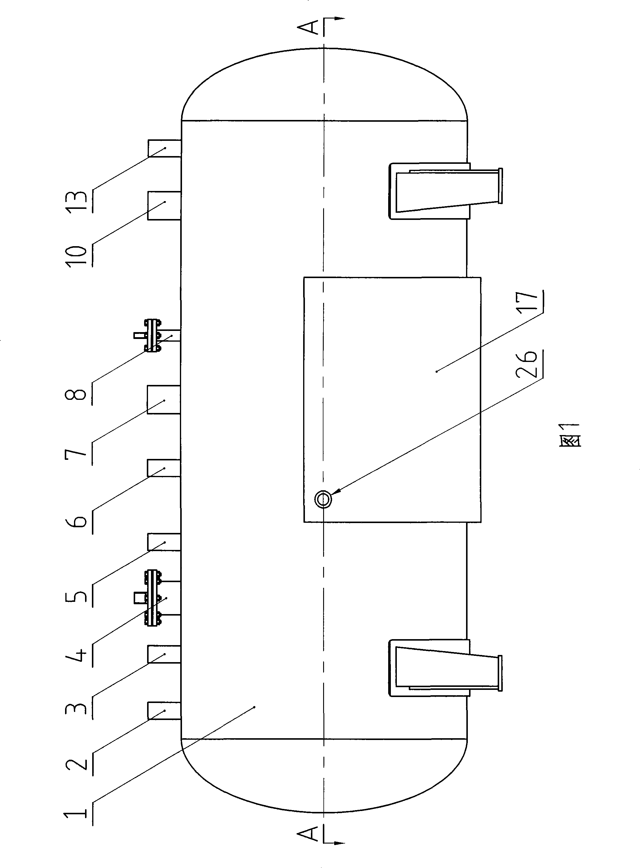
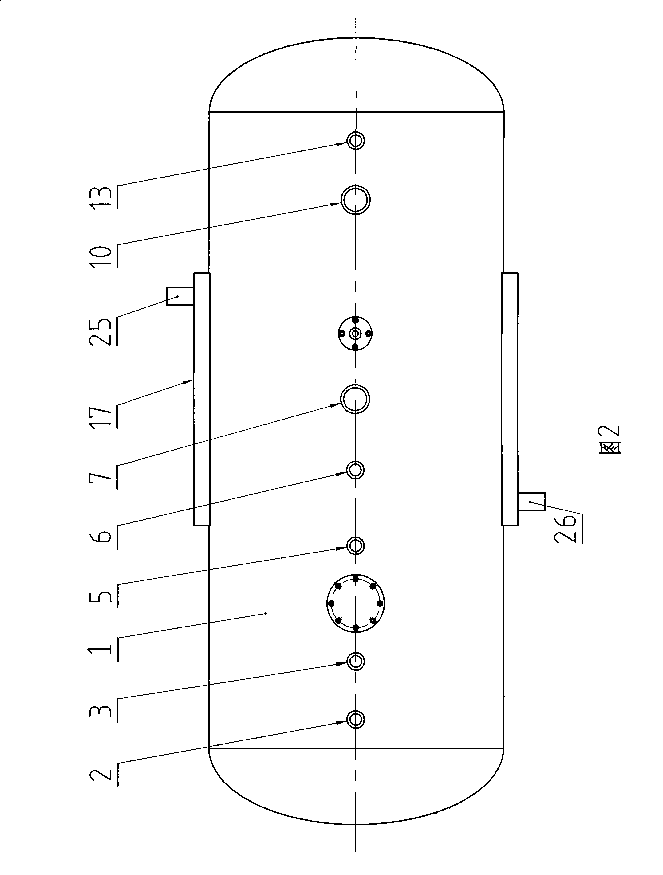
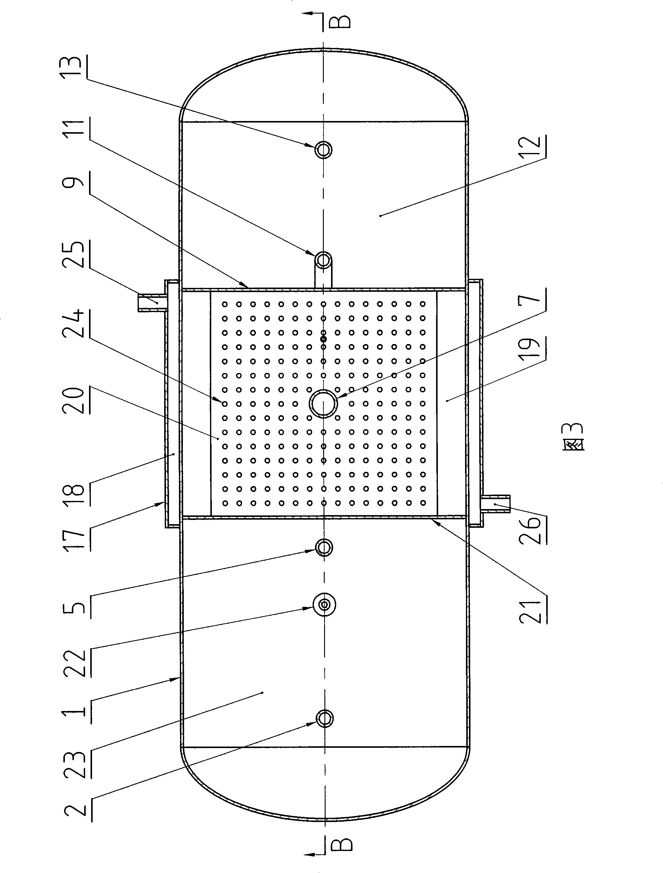
[0015]In Fig. 1, Fig. 2, Fig. 3, Fig. 4, Fig. 5 and Fig. 6, the horizontal tank body 1 is welded by a cylindrical body with a diameter of 2 meters rolled from a steel plate, an elliptical head and a support. , and its interior is welded with a partition 21 and a partition 9 composed of two circular steel plates to divide the interior of the horizontal tank 1 into three cavities, which are the raw material cavity 23, the vaporization cavity 19 and the residual liquid cavity 12, wherein The upper part of the circular partition 9 between the vaporization chamber 19 and the residual liquid chamber 12 is cut off to form a gap to connect the vaporization chamber 19 and the upper part of the residual liquid chamber 12; the oil inlet pipe 2 enters the raw material from the top of the raw material chamber 23 In the cavity 23, the distance between the end nozzle and the bottom of the raw material cavity 23 is 20-200 mm. The function of the oil inlet pipe 2 is to transport the liquid ligh...


PUM


Abstract

A liquid light hydrocarbon bubble vaporizer comprises a horizontal tank body. Two baffle plates are fixedly arranged in the horizontal tank body to separate the inside of the horizontal tank body into three cavities which are respectively a raw material cavity, a vaporizing cavity and a residual liquid cavity, wherein, the raw material cavity is fixedly provided with a vapor phase tube, an oil inlet tube and an oil outlet tube; the vaporizing chamber is fixedly provided with an air tube, an oil supply tube and a temperature measuring connection tube, the lower part of the vaporizing cavity is fixedly provided with a laminated air disk distributed with a plurality of through holes, the end tube mouth of the air tube is arranged under the air disk; the residual liquid cavity is fixedly provided with an oil pumping tube and an overflow tube, the vaporizing cavity is communicated with the upper part of the residual liquid cavity, and the vaporizing cavity or the residual liquid cavity is fixedly provided with a fuel gas outlet tube. The bubble vaporizer is one of the main devices in a light hydrocarbon mixed fuel gas supply system which takes liquid light hydrocarbon as a raw material to produce the light hydrocarbon mixed fuel gas.

Description

Technical field [0001] The invention relates to a bubbling vaporizer for producing light hydrocarbon mixed gas with liquid light hydrocarbon as raw material, in particular to a bubbling vaporizer for producing light hydrocarbon mixed gas with stable light hydrocarbon as raw material. Background technique [0002] The bubbling carburetor is one of the main equipment in the light hydrocarbon mixed gas supply system. The Chinese patent authorization announcement number is CN2475945Y. The date of the authorization announcement is February 6, 2002. The name of the utility model is: stable light hydrocarbon vaporizer. In the authorization announcement Disclosed is a stable light hydrocarbon vaporizer. The vaporizer is a bubbling vaporizer composed of a horizontal tank. Its disadvantage is that the structure is particularly complicated and the manufacturing cost is high. At the same time, the vaporizer needs to be additionally equipped to store liquid light hydrocarbons. The raw ma...

Claims


Application Information

Patent Timeline
IPC IPC(8): F23K5/22
Inventor 史俊和
Owner 张路
Why Eureka
Try Eureka