
Laser apparatus for patterning at light guide plate of back light unit and method for forming patterns using thereof

A technology of a backlight unit and a laser device, applied in the directions of light guides, optical elements, lighting devices, etc., can solve the problems of reduced reproducibility of graphic shapes, large CAD data capacity, consumption, etc., and achieve the effect of rapid composition

Inactive Publication Date: 2009-02-11
주비젼텍 +1
View PDF0 Cites 0 Cited by
  • Summary
  • Abstract
  • Description
  • Claims
  • Application Information

AI Technical Summary

Problems solved by technology

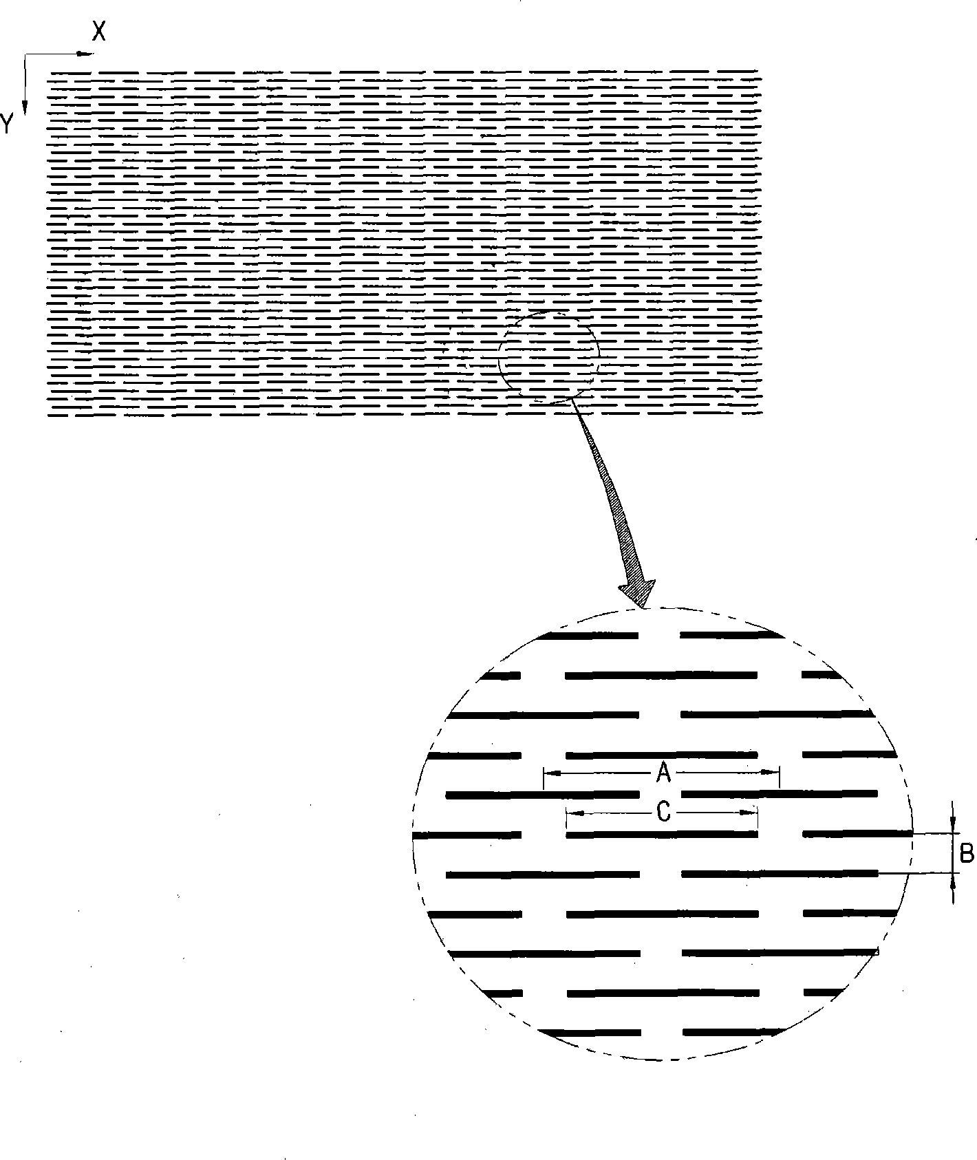
[0008] First of all, the mechanical cutting method using diamond has the following disadvantages: its speed is relatively slow, which reduces productivity, light cannot be scattered uniformly due to the roughness of the processed surface, and the reproducibility of reproducing the desired pattern form as it is is reduced
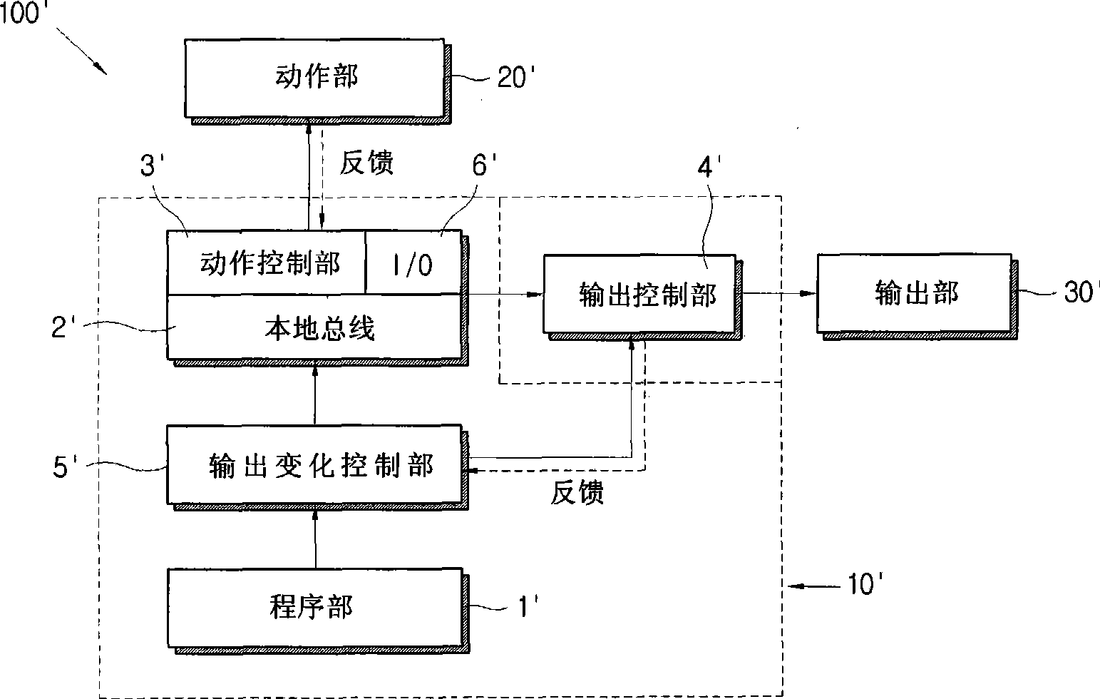
[0027] The above-mentioned "rest period" t5-t6 does not occur when manufacturing a light guide plate for small-sized liquid crystal displays in which the frequency of changing the laser duty cycle for each line and its variation range are small, but when manufacturing requires a lot of changes in the laser duty cycle When using the light guide plate of a large liquid crystal display device, as long as the above-mentioned past control system 10' is used, it will inevitably occur
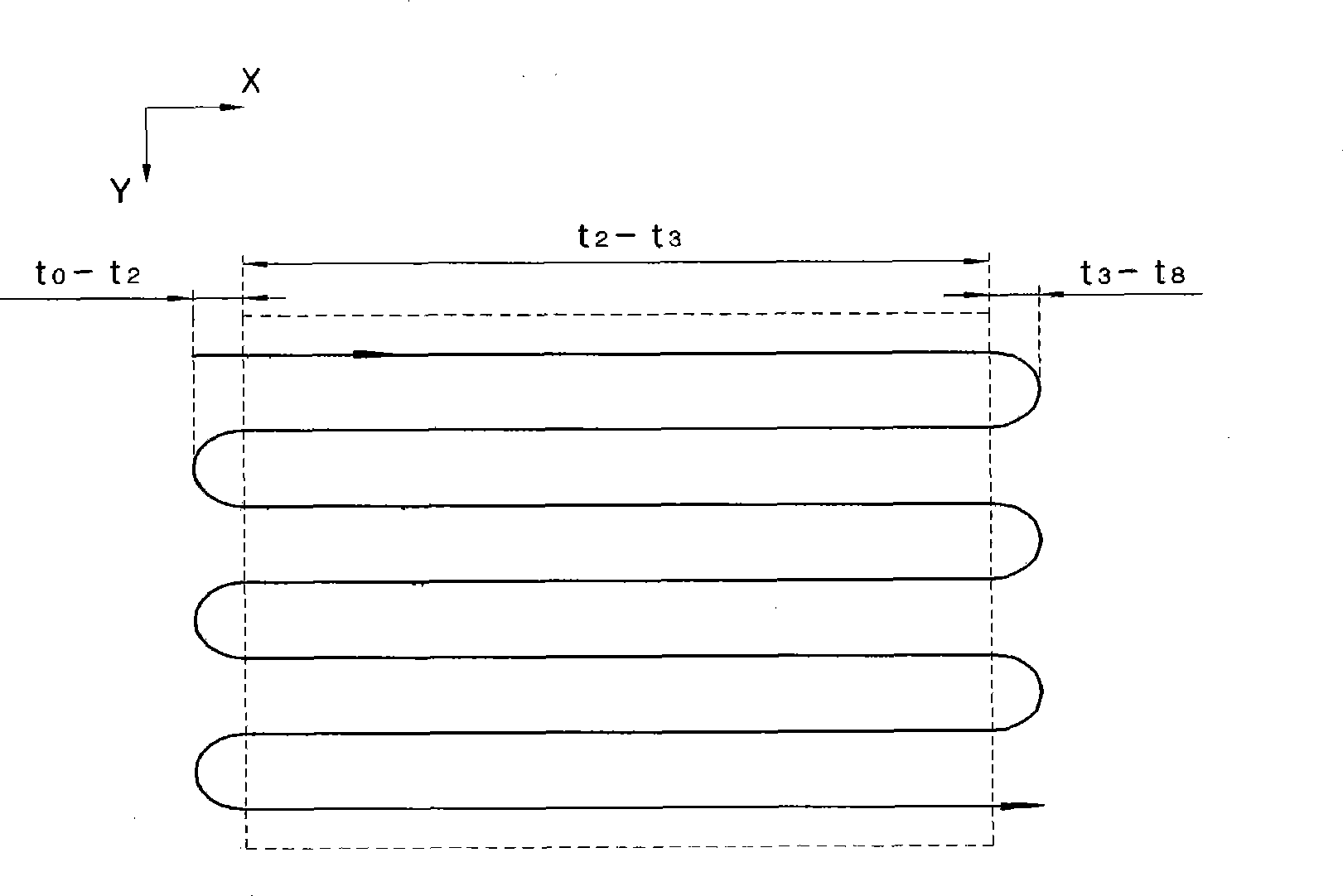
[0028] Generally speaking, the acceleration period takes about 60ms, and the stabilization period takes about 10ms.
However, when the control method based on the above-mentioned conventional system is applied, the output change process takes about 100 ms to several seconds, so a rest period of at least 30 ms or more is required
[0029] Another reason why the above-mentioned output change process is delayed is that the CAD data capacity of the graphic designed by the user at the beginning is too large, no matter how high the processing speed of the local bus is applied, the data arrangement work is performed during the execution of the composition, thereby reading the corresponding data. The value of 1 line data of a specific Y coordinate can only take time

Method used


Image

  • Laser apparatus for patterning at light guide plate of back light unit and method for forming patterns using thereof
  • Laser apparatus for patterning at light guide plate of back light unit and method for forming patterns using thereof
  • Laser apparatus for patterning at light guide plate of back light unit and method for forming patterns using thereof

Examples


Embodiment Construction

[0059] Hereinafter, the light guide plate patterning laser device for the backlight unit of the present invention and the light guide plate patterning method for the backlight unit using it will be described in detail with reference to the accompanying drawings.

[0060] Figure 4a It is a cross-sectional view of the light guide plate made by the light guide plate patterning method for the backlight unit of the present invention; FIG. 4b is a curve showing the contour line of the pattern depth based on the method.

[0061] Such as Figure 4a As shown, the light guide plate manufactured by the light guide plate patterning method for the backlight unit of the present invention is characterized in that the depth of the formed pattern has a contour line that changes as the Y coordinate increases away from the light source, thereby making the light emitted from the light source The light has the same brightness after being reflected.

[0062] As shown in Figure 4b, the above Figure 4a...


PUM


Abstract

The invention relates to a laser apparatus for patterning at light guide plate of back light unit and method for forming patterns at light guide plate of the back light unit using thereof, the laser apparatus comprises an output section emitting laser according to output signal oscillation, and forming patterns on plane light guide plate composed of X axis and Y axis, wherein the position equipped with light source is taken as initial point of Y axis; an action section for moving the output section according to action signal; a control system for controlling the output section and the action section. The control system comprises a program section for executing program about action of the output section and laser output; a local bus line linking with the program to receive pattern data of each 1 line of X axis corresponding with special Y coordinate of the light guide board to process; the action control section controlling action with data received from the local bus line. Wherein the action control and output control section are loaded on a local bus line for real-time control, referred patterning method herein employs the laser apparatus.

Description

Technical field [0001] The present invention relates to a patterning laser device and a patterning method that uses a laser device to form patterns on the surface of a light guide plate. More specifically, it relates to including an action control unit and an output control unit installed together on a local bus, which can be processed in a short time. A laser device of a multi-signal control system; and relates to a patterning method that uses the laser device to produce a light guide plate with higher reliability and a higher yield rate. Background technique [0002] In the field of flat panel display technology, the most widely commercialized and practical liquid crystal display, because it cannot emit light by itself, it is necessary to install a light-emitting device called a back light unit. The performance of the liquid crystal display depends not only on its own The characteristics also depend to a large extent on the performance of the above-mentioned backlight unit. [...

Claims


Application Information

Patent Timeline
IPC IPC(8): G02B6/00G02F1/13357G02F1/1333B23K26/00C03C23/00F21V8/00F21S2/00G02F1/1335
CPCG02B6/0061G02F1/133516G02F1/133524G02F1/133615
Inventor 申景湜金相佑申英一
Owner 주비젼텍
Learn More