Cutting head for high-speed low-layer cutting lathe

A cutting and low-level technology, applied in the field of fabric automatic cutting equipment, can solve the problems of cumbersome tool change and adjustment of knife setting work, cutting waste fabrics, single function of cutting head, etc., to ensure cutting accuracy and smoothness, and reduce usage Cost, the effect of improving cutting efficiency

Inactive Publication Date: 2009-02-18
杭州柯瑞自动化技术有限公司
View PDF0 Cites 15 Cited by
  • Summary
  • Abstract
  • Description
  • Claims
  • Application Information

AI Technical Summary

Problems solved by technology

The existing so-called low-level cutting bed produced in China is simply to add a cutting knife to the paper pattern cutting machine, and the knife can be dropped at a fixed height through a servo motor. The fabric cannot be cut, especially the large-format fabric cutting (the flatness of the large-format table is difficult to guarantee), the scope of use is limited, and it cannot be applied to the urgent needs of low-level cutting machines in industries such as large toy inflatable models and rowing shipbuilding. industry, only small-format cutting is possible, and has little practical significance, and is not a low-level cutting machine in the true sense.
Foreign low-level cutting machines, most of the cutting heads have single functions, fewer types of knives, and no red light preview function
Cutting different fabrics requires cumbersome tool change and adjustment of knife setting work, and it is easy to cut waste fabrics and waste fabrics
The pen used is also very special and cannot be replaced with an ordinary pen. After the ink is used up, it can only be replaced with a pen produced by a foreign original factory, which is very expensive to use

Method used


Image

  • Cutting head for high-speed low-layer cutting lathe
  • Cutting head for high-speed low-layer cutting lathe
  • Cutting head for high-speed low-layer cutting lathe

Examples


Embodiment 1

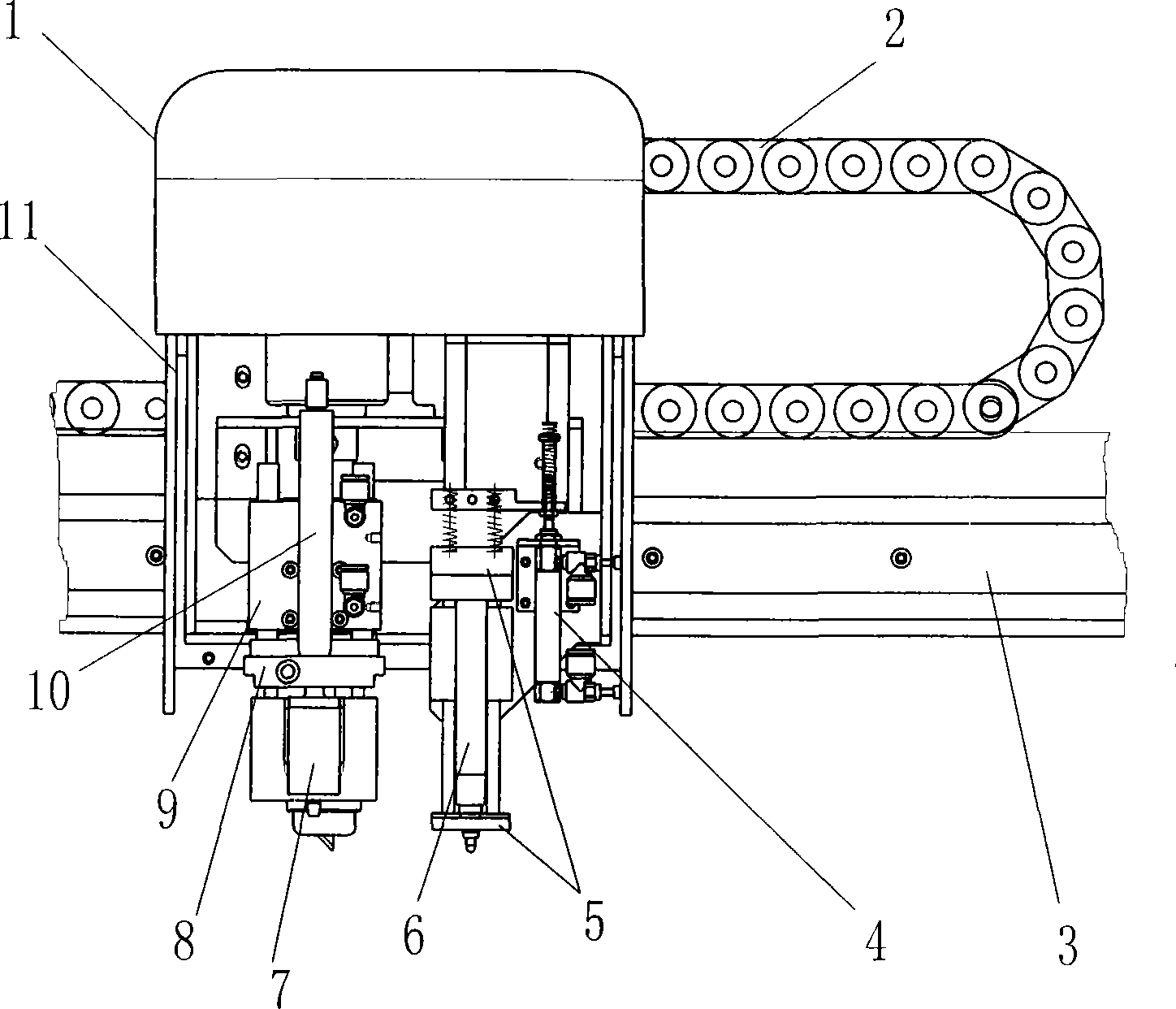
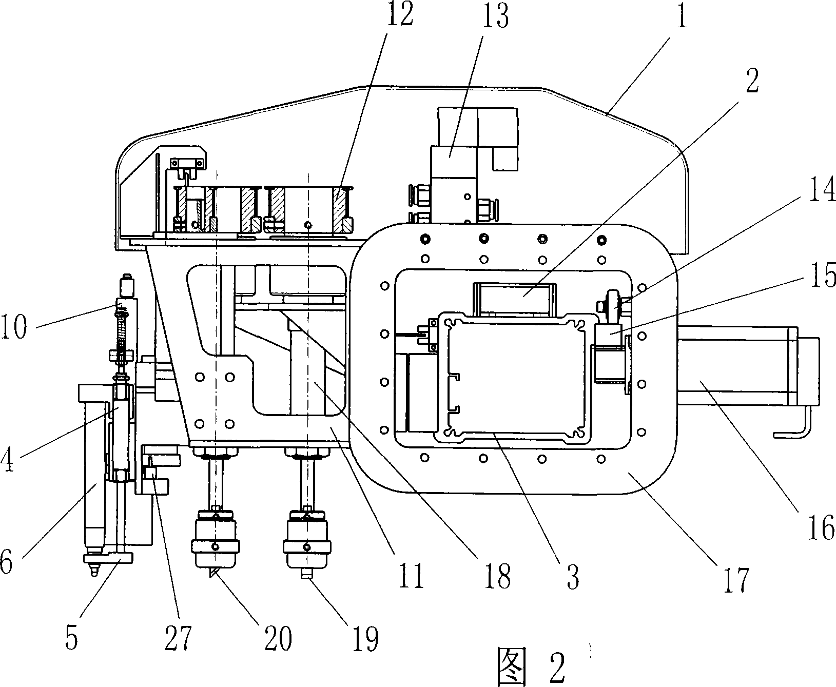
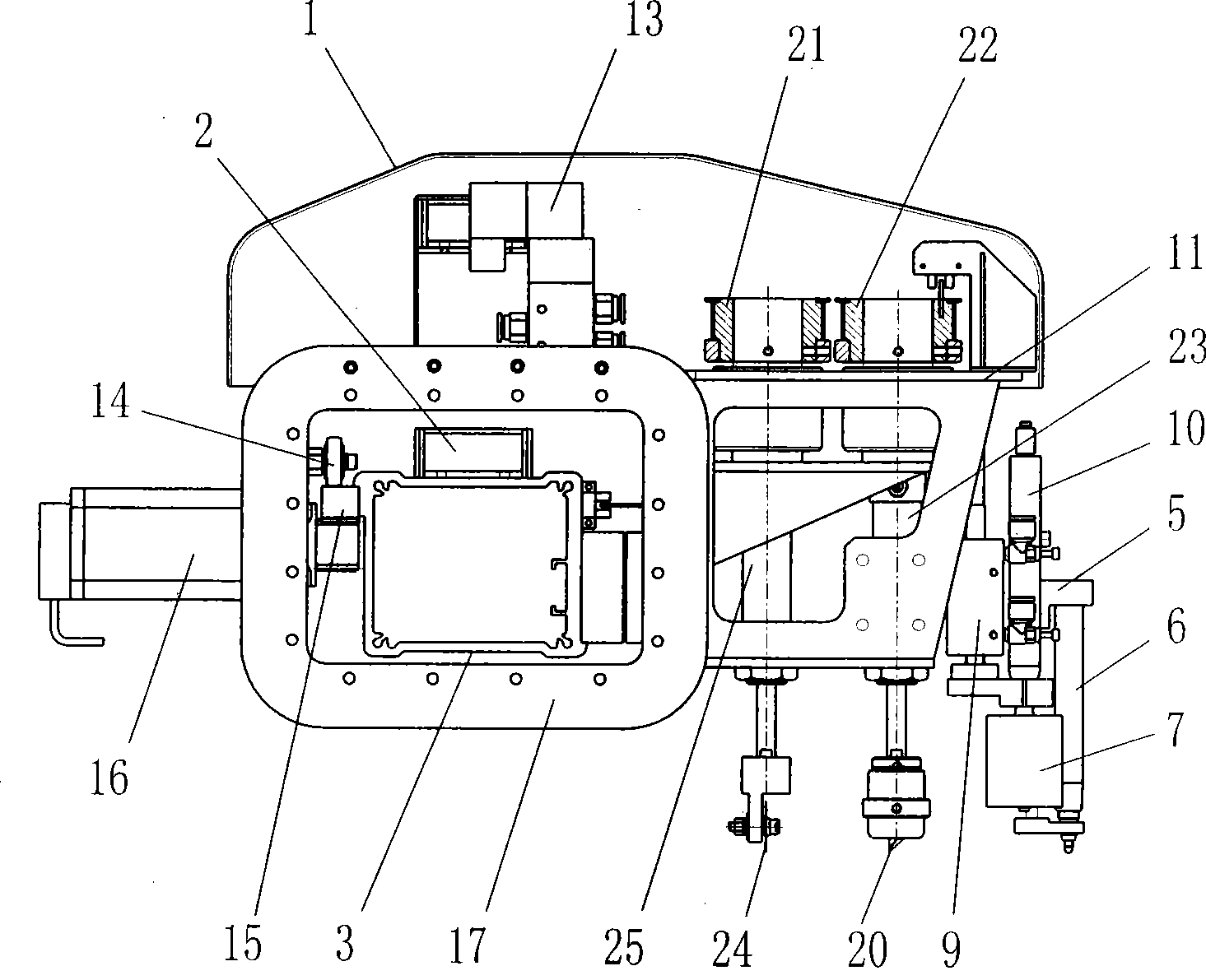
[0023] Such as Figure 1-Figure 4 A cutting head for a high-speed low-layer cutting machine shown, including a cutting head frame 11, on which a pen 6, a flat knife 19, a pointed knife 20, a round knife 24 and a punching drill are arranged. 7. The pen 6 is located on the pen holder 5, the pen holder 5 is connected to the vertical moving end of the pen-down cylinder 4, and the fixed end of the pen-down cylinder 4 is connected to the cutting head frame 11; the flat knife 19 is located on the flat The lower end of the piston rod of the knife cylinder 18, the flat knife cylinder 18 is vertically fixed on the cutting head frame 11, the piston rod upper end of the flat knife cylinder 18 is connected with the flat knife belt wheel which is arranged on the cutting head frame 11 in rotation 12 spline connection; described sharp knife 20 is located at the piston rod lower end of sharp knife cylinder 23, and described sharp knife cylinder 23 is vertically fixed on the cutting head frame ...


PUM


Abstract

The invention discloses a cutting head for a high-speed low-level cutting bed. The cutting head comprises a cutting head support, a pen, a plain knife, a sharp knife, a circular knife and a piercing drill, wherein the pencil is arranged on a pen stand which is connected to the upright moving end of a pen down cylinder; the fixed end of the pen down cylinder is connected to the cutting head support; the plain knife is arranged on the lower end of a piston rod of a plain knife cylinder; the plain knife cylinder is arranged on the cutting head support; the upper end of the piston rod of the plain knife cylinder is connected with a spline of a belt pulley of the plain knife, and the spline is rotationally arranged on the cutting head support; the sharp knife and the circular knife are arranged like the plain knife; the piercing drill is arranged on an output shaft of a piercing pneumatic motor; the piercing pneumatic motor is arranged on a piercing drill seat which is fixedly connected tothe upright moving end of a piercing cylinder; the fixed end of the piercing cylinder is connected with the cutting head support, wherein cylinders are all connected with an electromagnetic valve; belt pulleys are all in transmission connection with a servo motor of a rotary cutter; and the electromagnetic valve and the servo motor of the rotary cutter are arranged on the cutting head support andconnected with a control circuit. The technical proposal can realize multifunction large-scale cutting of various fabrics.

Description

technical field [0001] The invention belongs to the field of fabric automatic cutting equipment, in particular to a multifunctional cutting head for high-speed low-layer cutting bed. Background technique [0002] High-speed low-layer cutting bed is a kind of automatic fabric cutting machine, which belongs to computer CAD output equipment, and can be widely used in cutting fabrics such as clothing, shoemaking, bags, automobile interiors, aircraft interiors, large toy inflatable models, and rowing shipbuilding. Cutting is the necessary equipment to realize the integration of CAD and CAM in clothing, shoemaking and other industries. It can automatically cut various fabrics, leather, artificial leather, rubber, plastic film, plastic board, cardboard, etc. [0003] The high-speed low-level cutting bed is mainly composed of cutting table, cutting head, fabric adsorption system, X-direction transmission and sliding system, Y-direction transmission and sliding system and control sys...

Claims


Application Information

Patent Timeline
Patent Type & Authority Applications(China)
IPC IPC(8): B26D9/00B26D5/12B26D5/00A41H3/00A41H9/00D06H7/00
Inventor 王鹏魏兵伍郁杰白燕范宏炜汪战平苏冬
Owner 杭州柯瑞自动化技术有限公司
Why Eureka
Try Eureka