Fibre reinforced resin based composite material fin piece molding mould

A fiber-reinforced resin and composite material technology is applied in the field of forming molds for composite fins. The effect of good quality and reduced product porosity

Inactive Publication Date: 2009-02-18
HARBIN FRP INST
View PDF0 Cites 14 Cited by
  • Summary
  • Abstract
  • Description
  • Claims
  • Application Information

AI Technical Summary

Problems solved by technology

[0003] The purpose of the present invention is to solve the problem that the positioning surfaces of the upper and lower dies of the forming mold of the existing composite material fins have zero clearance, resulting in insufficient mold clamping and too tight sealing of the mold cavity, so that the air in the

Method used


Image

  • Fibre reinforced resin based composite material fin piece molding mould
  • Fibre reinforced resin based composite material fin piece molding mould
  • Fibre reinforced resin based composite material fin piece molding mould

Examples


specific Embodiment approach 1

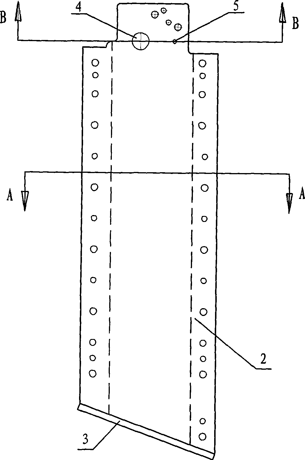
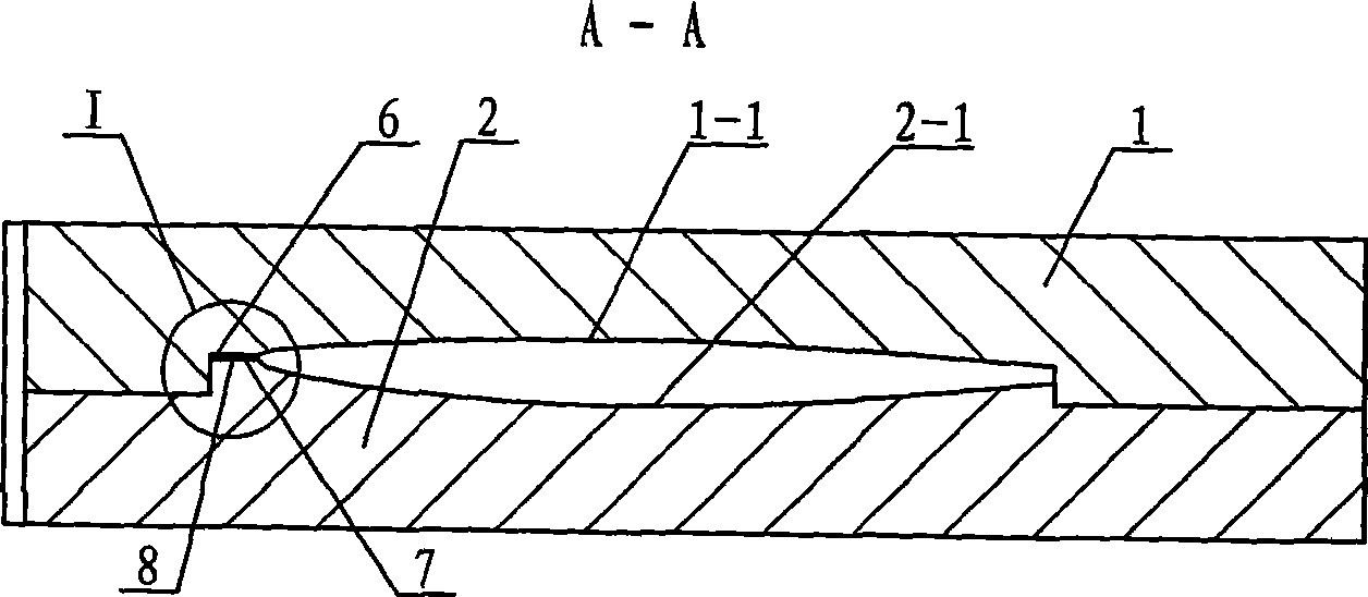
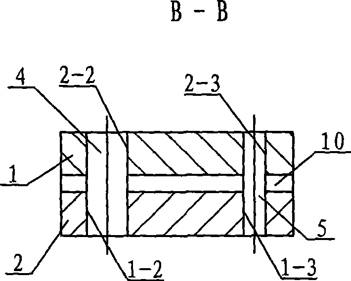
[0007] Specific implementation mode one: combine Figure 1 ~ Figure 4 Describe this embodiment, this embodiment includes upper mold 1, lower mold 2, limit plate 3, first positioning pin 4 and second positioning pin 5, the parting surface 6 of upper mold 1 and lower mold 2 is provided with upper Model groove 1-1, the parting surface 7 of lower mold 2 and upper mold 1 is provided with lower mold groove 2-1, a cavity is formed between upper mold groove 1-1 and lower mold groove 2-1, and a limit plate 3 Installed on the bottom slope of the upper die 1 and the lower die 2, the upper end of the upper die 1 is provided with a first positioning pin hole 1-2 and the second positioning pin hole 1-3, and the upper end of the lower die 2 is provided with a second Three positioning pin holes 2-2 and the fourth positioning pin hole 2-3, the first positioning pin 4 is arranged in the first positioning pin hole 1-2 and the third positioning pin hole 2-2, the second positioning pin 5 is arrang...

specific Embodiment approach 2

[0008] Specific implementation mode two: combination Figure 4 The present embodiment will be described. The width W of the overflow groove 8 of the present embodiment is 15 to 25 mm, and the depth h of the overflow groove 8 is 0.3 to 0.5 mm. The overflow groove 8 within the above numerical range can not only achieve the function of exhausting and discharging excess resin, but also does not affect the mechanical properties and appearance quality of the product. Other combinations and connections are the same as those in the first embodiment.

specific Embodiment approach 3

[0009] Specific implementation mode three: combination Figure 4 The present embodiment will be described. The width W of the overflow groove 8 of the present embodiment is 20 mm. This width is sufficient to ensure that the overflow tank 8 is exhausted and excess resin is discharged. Other combinations and connections are the same as those in the second embodiment.


PUM

PropertyMeasurementUnit
Widthaaaaaaaaaa
Depthaaaaaaaaaa

Abstract

The invention provides a molding die for fiber reinforced resin-based composite vanes. The invention relates to molding die for composite vanes, which aims to solve the problems that the prior composite vane molding die is insufficient in die assembly and too tight to seal die cavities, can not discharge air in a product, can not guarantee the geometrical size of the airfoil surface of a vane and the relative position of a vane handle, and causes that the product is large in porosity or has air holes on surface. A parting surface of an upper die and a lower die is provided with an upper model groove; a parting surface of the lower die and the upper die is provided with a lower model groove; a first positioning pin is arranged in a first positioning pinhole and a third positioning pinhole; a second positioning pin is arranged in a second positioning pinhole and a fourth positioning pinhole; and a gap between the parting surfaces of the upper die and the lower die is configured as a material overflow groove. The material overflow groove can ensure that the upper and lower dies are sufficient in die assembly; die cavities are incompletely sealed; the air in the product can be smoothly discharged; the geometrical size of the airfoil surface of the vane and the relative position of the vane handle are guaranteed; and the product is good in surface quality.

Description

technical field [0001] The invention relates to a molding die for a composite material wing. Background technique [0002] The wing is an important part to ensure the flight distance and accuracy of the product. The application of advanced composite materials on the wing can minimize the structural weight and improve product performance; at the same time, it can also meet some special performance requirements of the product, such as stealth performance , Pneumatic cutting, anti-corrosion, etc. The airfoil shape of the wing must have high geometric precision, high structural strength and rigidity to ensure the flight performance of the product. The forming methods of the wing mainly include assembly type and integral type. Assembled type means that the skin and frame of the wing are produced separately, and then bonded together; , to overcome the problem of discontinuous fibers of the assembled upper and lower skins, and reduce the subsequent bonding and assembly problems. ...

Claims


Application Information

Patent Timeline
IPC IPC(8): B29C33/30B29C33/10B29C33/38B29C70/54B29L31/08
Inventor 路明坤梁岩石建军韩丽华曲艳双杨永生
Owner HARBIN FRP INST
Why Eureka
Try Eureka