Livestock and poultry facility cultivation surroundings monitoring method

An environmental monitoring and facility technology, applied in the directions of comprehensive factory control, comprehensive factory control, electrical program control, etc., can solve the problems of inconvenient promotion and application, low performance and price ratio, and no automatic control function.

Inactive Publication Date: 2009-02-18
SOUTHEAST UNIV
View PDF0 Cites 14 Cited by
  • Summary
  • Abstract
  • Description
  • Claims
  • Application Information

AI Technical Summary

Problems solved by technology

[0002] At present, domestic monitoring methods for the breeding environment of livestock and poultry facilities mainly rely on the experience of the breeders for manual observation, and occasionally use the temperature and humidity meter for manual measurement, so they lack due scientificity
In 2004, the first device that used wired methods to monitor the cultivation and growth environment of plant facilities appeared in China, and achieved certain results, but this device lacks control functions
[0003] (1) Large system investment, high cost, and low performance-price ratio
[0004] (2) The cable reuse rate of the system is low and the complexity is high, so the system has a high

Method used


Image

  • Livestock and poultry facility cultivation surroundings monitoring method
  • Livestock and poultry facility cultivation surroundings monitoring method
  • Livestock and poultry facility cultivation surroundings monitoring method

Examples


Embodiment 1

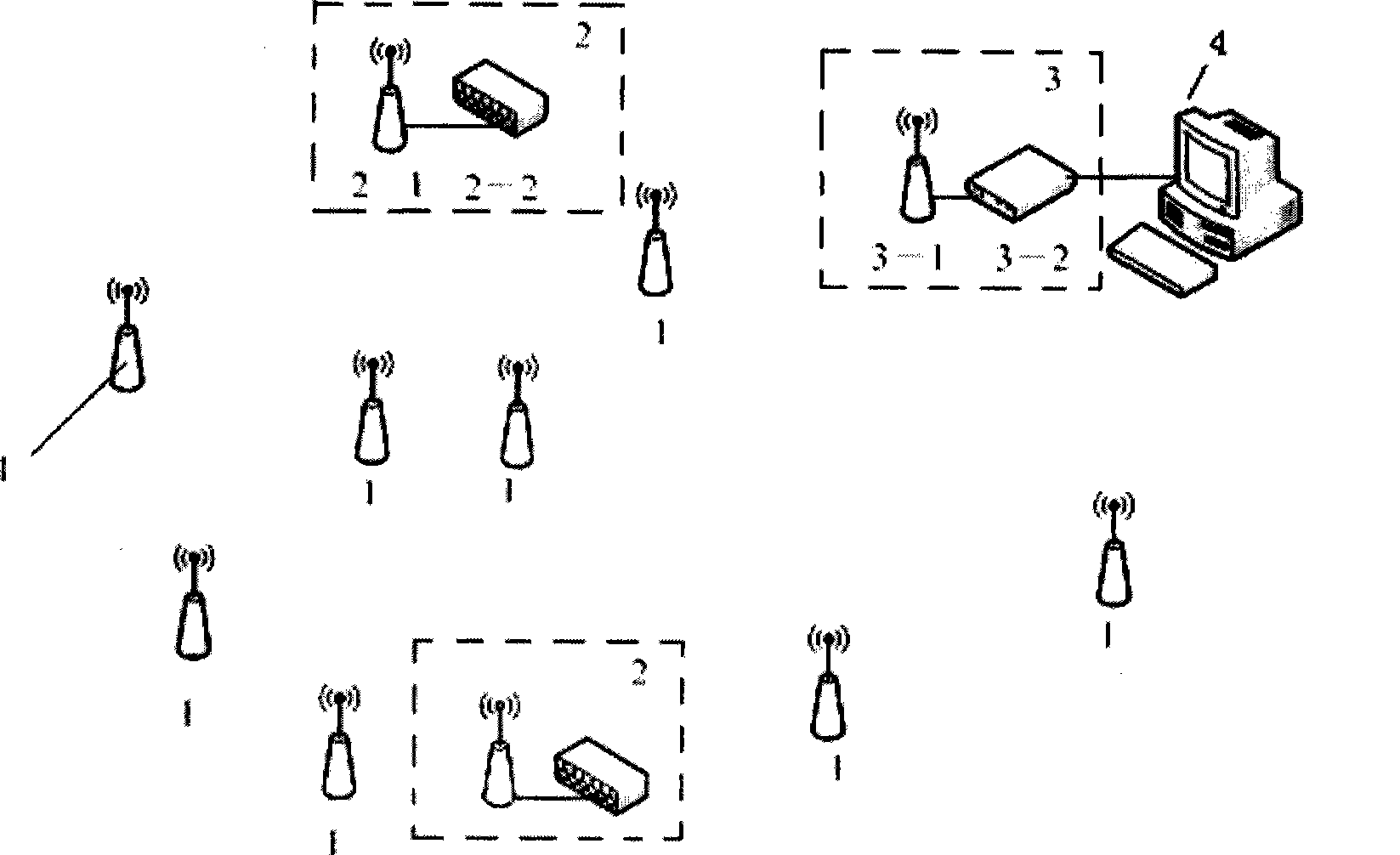
[0150] Such as figure 1All nodes (including sensor nodes, control nodes and base stations) of the livestock and poultry facility breeding environment monitoring system shown are powered on and initialized. The sensor node initializes its wireless transceiver unit to make it in the information receiving state; initializes the sensor unit and prepares to collect data. The control node initializes its wireless transceiver unit so that it is in the information receiving state, initializes the controller, prepares to collect the state data of the controlled device and control the start and stop of the controlled device. The base station initializes its wireless transceiver unit, ready to start the system.

[0151] Such as Figure 6 As shown, the monitoring method includes the following steps:

[0152] 1.1. The network node is powered on and initialized;

[0153] 1.2. The base station sends a system pre-start data packet and starts the system start timer;

[0154] 1.3. The netw...

Embodiment 2

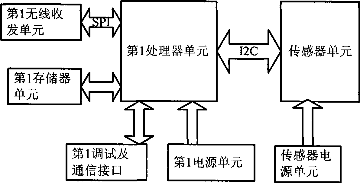
[0186] The sensor node collects the parameter information of the monitoring environment according to a certain time period, and sets the network synchronization timer cycle and network synchronization conditions after receiving the start data packet sent by the base station. The network synchronization timer is used for time synchronization of the network. Each node is set with a network synchronization timer to facilitate the synchronization of the entire network and effectively realize the cooperative work of the nodes. When the set time of the network synchronization timer is up, start the network synchronization timer again and start collecting data. After the data collection is completed, select the best route to send the data and update the routing information. After the data is sent, the sensor node sets its processor unit to a sleep state, turns off the sensor unit, and turns off its wireless transceiver unit, so that the sensor node is in a low power consumption state,...

Embodiment 3

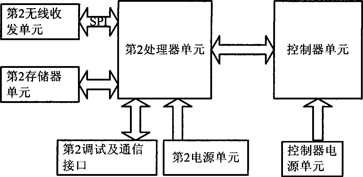
[0210] The control node receives the startup data packet sent by the base station, sets the period of the network synchronization timer, and starts the network synchronization timer. If the time set by the network synchronization timer expires, it starts to collect the status data of the controlled device. Optimal routing, start the data sending task, and realize the monitoring of the equipment. After the data transmission is completed, the routing information is updated and the dynamic routing is maintained. The control node is powered by a wired power supply, and the entire node does not need to sleep. The device monitoring package mainly includes the status information of the controlled device, and its package type is 0x05. The control data packet mainly identifies the name of the controlled device and the state of the controlled device. The source address identifies the node id of the controlled device, and the destination address identifies the node id of the next hop. T...


PUM


Abstract

Disclosed is a culture environment monitoring method of a livestock facility, comprising the following steps: sensing nodes collect environmental parameter information in real time, control nodes collect running state information of a controlled device, and the information is transmitted through other sensing nodes or control nodes by a multi-hop mode, and monitoring data are processed by a plurality of nodes in the transmitting process and are routed to a base station and a monitoring site by the multi-hop mode; and the base station receives the environmental parameter information and the running state information of the controlled device transmitted by the sensing nodes and the control nodes through a communication module, a computation module is in serial communication with the communication module to obtain physical quantity data of various parameters. The base station transmits the physical quantity data to the monitoring site through serial ports on the one hand, and a user interface displays environmental data and the state of the controlled device; and on the other hand, the base station obtains a control command through the physical quantity data of the parameters and a control algorithm, and the control command is transmitted to the control nodes for controlling the controlled device by the multi-hop mode, so as to reach the purpose of environment monitoring.

Description

technical field [0001] The invention relates to an environment monitoring method, which belongs to the field of livestock and poultry facility breeding environment monitoring, in particular to a method for realizing wireless sensor network monitoring based on a wireless communication mode. Background technique [0002] At present, domestic monitoring methods for the breeding environment of livestock and poultry facilities mainly rely on the experience of the breeders for manual observation, and occasionally use the temperature and humidity meter for manual measurement, so they lack due scientificity. In 2004, the first equipment that used wired methods to monitor plant cultivation and growth environment appeared in China, and achieved certain results, but this equipment lacks control functions. It can be used to monitor the breeding environment of livestock and poultry facilities within a certain range and to a certain extent, but from the perspective of wider application si...

Claims


Application Information

Patent Timeline
IPC IPC(8): G05B19/418H04L29/08H04L12/28
CPCY02P90/02
Inventor 陈俊杰郝永志
Owner SOUTHEAST UNIV
Why Eureka
Try Eureka