Reducing reagent nozzle for denitration by SNCR method

A reducing agent and nozzle technology, which is applied in the field of nozzles for injecting reducing agent, can solve the problems of uneven distribution of droplets, short range, rising cost, etc., and achieve the effects of good penetration performance, narrow temperature range and improved efficiency.

Inactive Publication Date: 2009-02-25
JIANGSU ZHONGKE ENERGY SAVING ENVIRONMENTAL PORTECTION TECH
View PDF0 Cites 26 Cited by
  • Summary
  • Abstract
  • Description
  • Claims
  • Application Information

AI Technical Summary

Problems solved by technology

At present, judging from the application of the SNCR method in engineering, most of them use pneumatic atomization injection equipment, such as spray guns and wall nozzles; the spray guns are directly inserted into the reaction furnace, which can reach about half the length of the furnace, and the nitrogen reducing agent is directly sent into the furnace. However, it needs to be equipped with supporting equipment such as water cooling, automatic mechanical retraction, rotating ash removal, high temperature and constant humidity, water cut-off alarm, etc., which makes the cost rise and maintenance is difficult
Although the wall nozzle has a simple structure, easy operation and maintenance, and is not easy to be damaged, it is difficult for the spray droplets to penetrate deep into the furnace.
The outlets of the nozzles used in the above two types of equipment are trumpet-shaped, so that the shape of the sprayed reducing agent droplets is usually a solid conical shape. Short, low denitrification efficiency; at the same time, the nozzle is easy to block, the momentum of the jet is insufficient, the spray penetration is not strong and the mixing is uneven

Method used


Image

  • Reducing reagent nozzle for denitration by SNCR method
  • Reducing reagent nozzle for denitration by SNCR method
  • Reducing reagent nozzle for denitration by SNCR method

Examples


Embodiment Construction

[0016] Below in conjunction with accompanying drawing and embodiment the present invention is described in further detail:

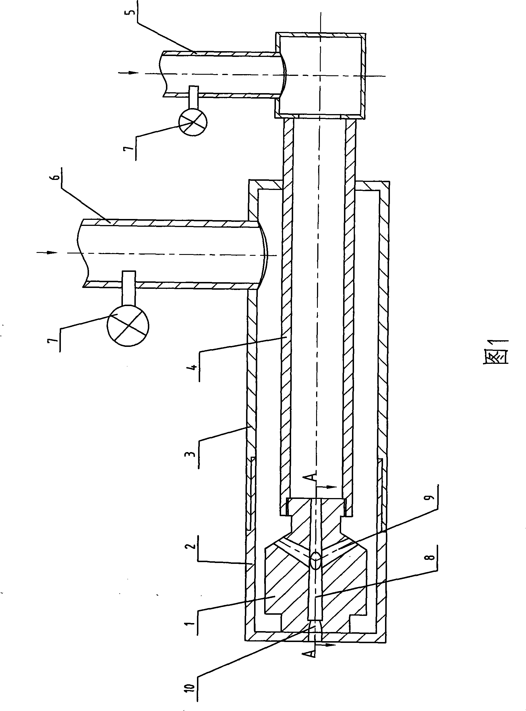
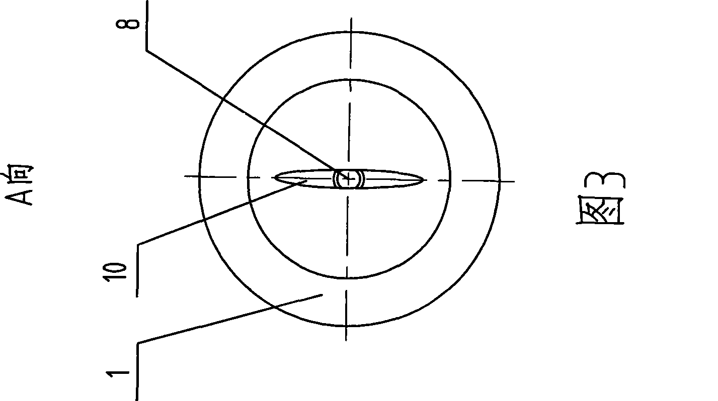
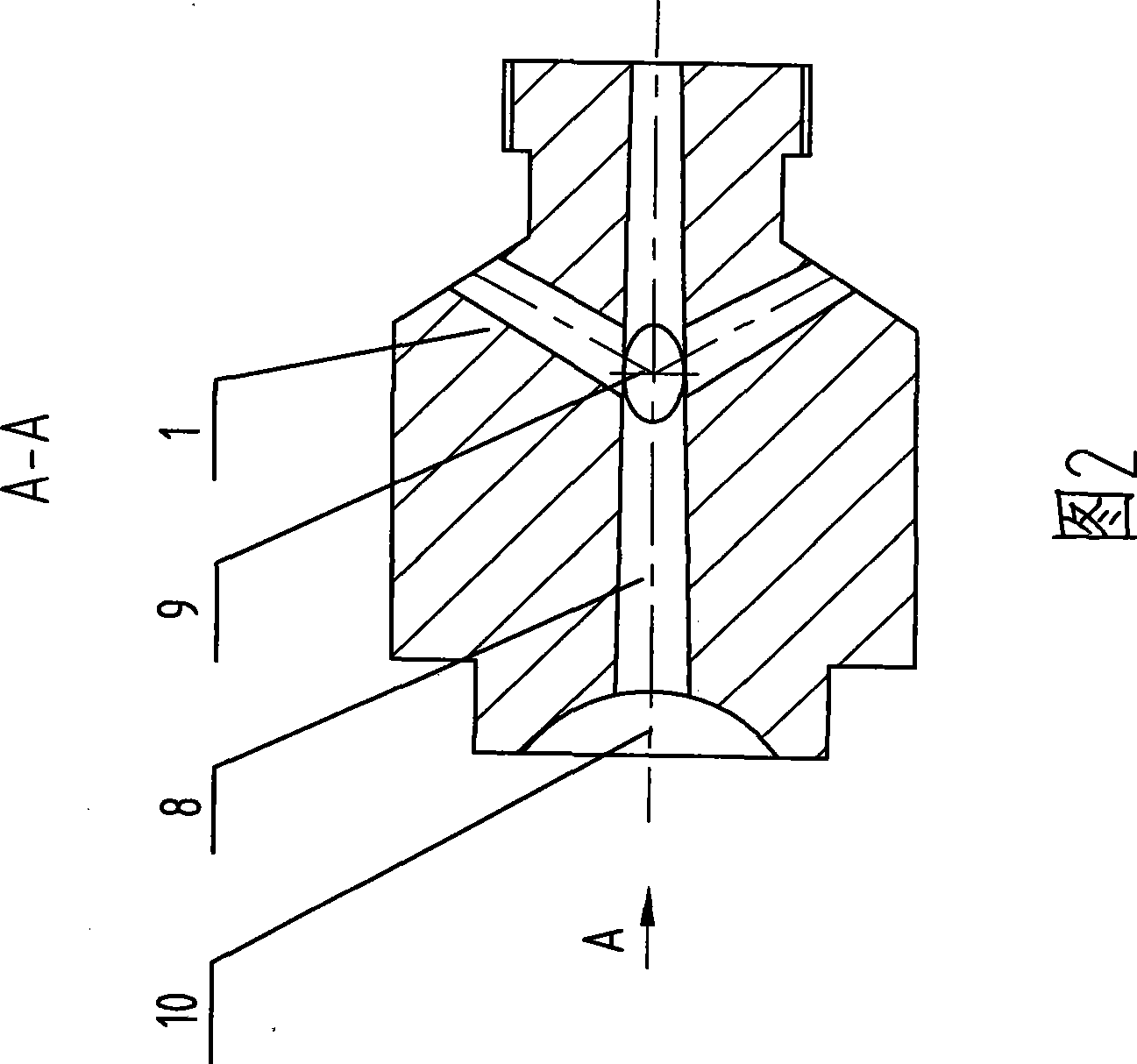
[0017] The present invention comprises a main pipe 4, a secondary pipe 3, a ferrule 2, a liquid flow pipe I5, a liquid flow pipe II6 and a nozzle 1, the ferrule 2 and the secondary pipe 3 are connected by threads to form a relatively airtight space, and the front end of the main pipe 4 is equipped with a nozzle 1, and placed in the auxiliary pipe 3, the front end of the nozzle 1 is in contact with the ferrule 2; the rear end of the main pipe 4 is connected with the liquid flow pipe I5 with a pressure gauge 7; the auxiliary pipe 3 is connected with the pressure gauge 7 The liquid flow tube II6 is connected; the nozzle 1 is provided with a mixing hole 8 passing through the main pipe 4 in the axial direction. The nozzle 1 is also provided with four branch holes 9 communicating with the mixing hole 8 and the auxiliary pipe 3. The branch holes 9 are also tape...


PUM


Abstract

The present invention provides a reducer nozzle used for denitration by an SNCR method. The reducer nozzle comprises a main pipe, an accessory pipe, a cutting ferrule, liquid pipes and a nozzle. The cutting ferrule is connected with the accessory pipe by screw threads to form a relative closed space. The front end of the main pipe is equipped with the nozzle and is arranged in the accessory pipe. The front end of the nozzle is contacted with the cutting ferrule. The back end of the main pipe is communicated with the liquid pipe I which is provided with a manometer. The accessory pipe is communicated with the liquid pipe II which is provided with the manometer. The nozzle is provided with a mixing hole which runs through the main pipe axially and is provided with a plurality of branch holes of the accessory which are communicated with the mixing hole and the accessory pipe. Olivary spray ports are arranged at the nozzle at a liquid outlet of the mixing hole and the cutting ferrule. The reducer nozzle has reasonable structure; when reducer penetrates an oven, the temperature range is narrow, the penetrable performance is good, and the spray distance is long; the reducer nozzle can also effectively control the granularity of atomized particles of the reducer and the vaporizing time of atomized liquid drops; and the reducer is mixed with NOx in smoke uniformly to improve the efficiency of denitrating the smoke.

Description

technical field [0001] The invention relates to flue gas purification and denitrification equipment, in particular to a nozzle for injecting a reducing agent for removing NOx in flue gas by SNCR method. Background technique [0002] At present, in order to purify NOx in flue gas and realize denitration emission, there are mainly two kinds of measures: combustion control and post-combustion control. Among them, selective catalytic reduction (SCR) and selective non-catalytic reduction (SNCR) are widely used in industrial production to control and eliminate NOx in flue gas after combustion. Both SCR and SNCR methods use NHx as the reducing agent to spray into the reaction furnace with "selectivity" under the action of catalyst or no catalyst, and react with NOx in the flue gas to generate non-toxic and pollution-free nitrogen (N 2 ) and water (H 2 O). The reaction formula is as follows: [0003] 4NH 3 +4NO+O 2 =4N 2 +6H 2 o [0004] 8NH 3 +6NO 2 =7N 2 +12H 2 o [...

Claims


Application Information

Patent Timeline
Patent Type & Authority Applications(China)
IPC IPC(8): B01D53/79B01D53/56B05B1/04B05B7/04
Inventor 俞进旺宋正华陈开明杨正平何美华袁海燕
Owner JIANGSU ZHONGKE ENERGY SAVING ENVIRONMENTAL PORTECTION TECH
Why Eureka
Try Eureka