Apparatus and method for remotely measuring subgrade settlement by laser

A remote measurement and laser measurement technology, applied in the direction of measuring devices, optical devices, roads, etc., can solve the problems of low measurement efficiency, low detection accuracy, pipeline leakage, etc., to reduce the measurement workload, avoid manual errors, The effect of improving measurement efficiency

Inactive Publication Date: 2009-02-25
BEIJING JIAOTONG UNIV
View PDF1 Cites 39 Cited by
  • Summary
  • Abstract
  • Description
  • Claims
  • Application Information

AI Technical Summary

Problems solved by technology

This system takes a point outside the subgrade, that is, the position of the observation cup, as the reference point. Its shortcoming is that the measurement point and the reference point are connected by a pipeline. If the flexible pipeline expands or the pipeline leaks due to external factors, the Affect the accuracy of the measurement results
[0009] To sum up, the followi

Method used


Image

  • Apparatus and method for remotely measuring subgrade settlement by laser
  • Apparatus and method for remotely measuring subgrade settlement by laser
  • Apparatus and method for remotely measuring subgrade settlement by laser

Examples


Embodiment 1

[0041] The following introduces the remote measurement of subgrade internal settlement device realized by laser measurement technology.

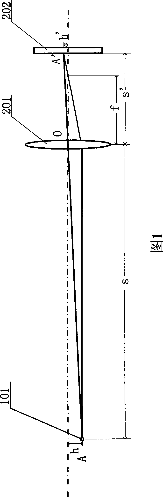
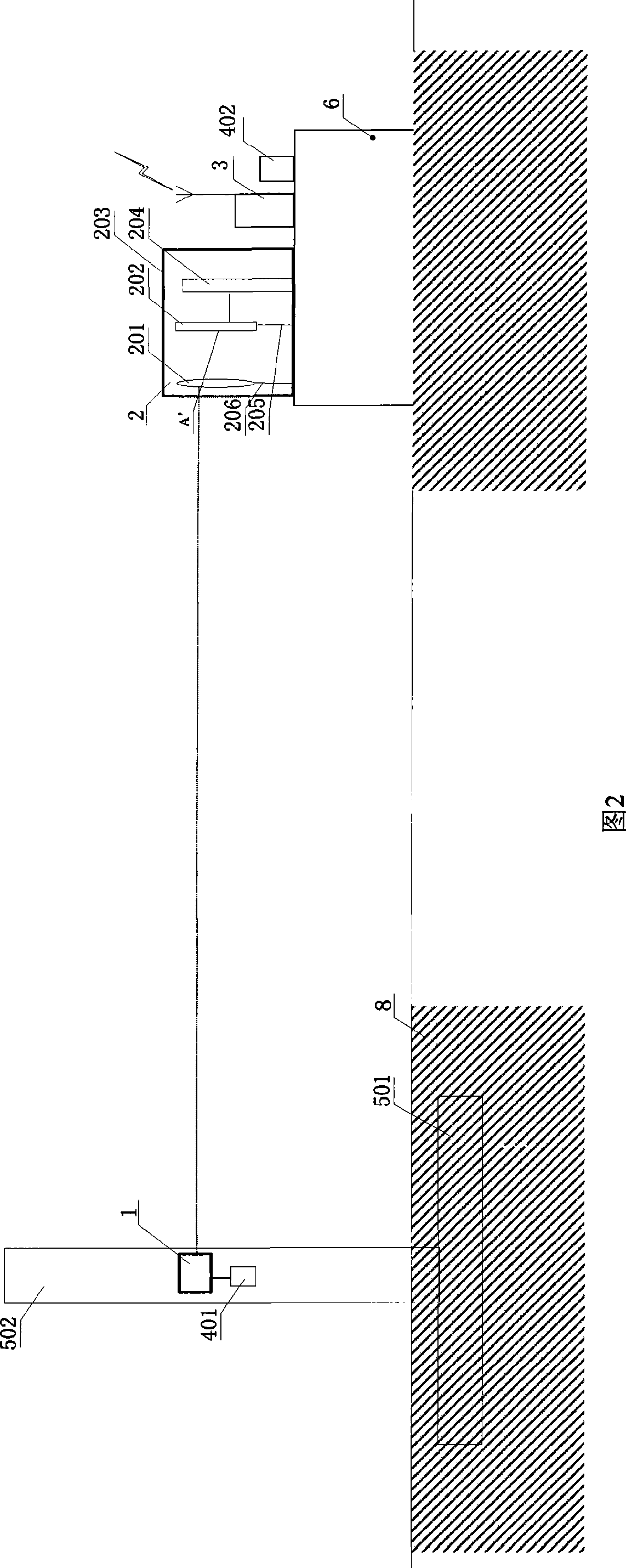
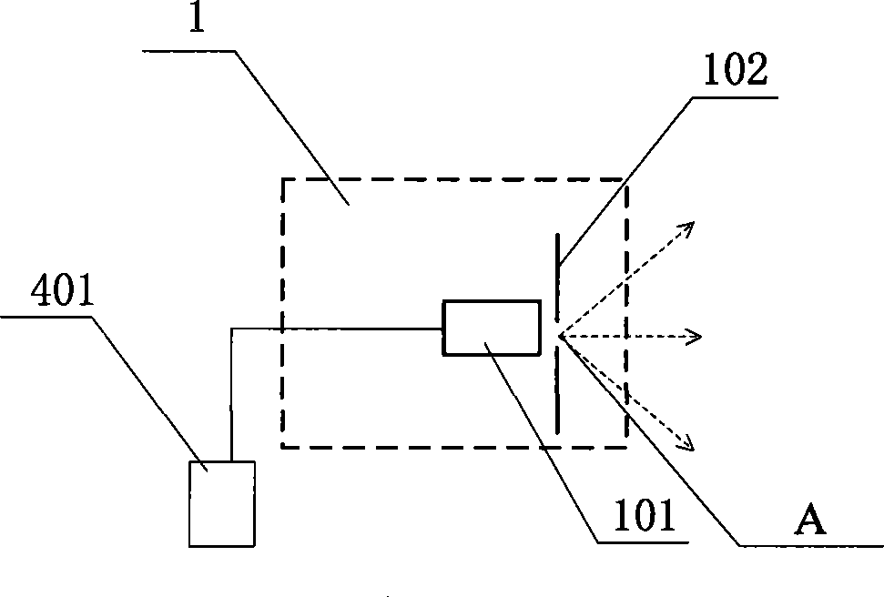
[0042] As shown in Figure 2, the laser remote measurement subgrade internal settlement device is mainly composed of a subgrade settlement measurement unit, a measurement signal transmission unit, a central processing unit, and a power supply module. The measurement signal transmission unit and the central processing unit are wired or wirelessly. connect. Among them, the roadbed settlement measurement unit is the basis for realizing the laser remote measurement of the internal settlement of the roadbed, and it includes four parts: a point light source 1, a laser measurement unit 2, a settlement detection pile 5 and a fixed observation pile 6.

[0043] The point light source 1 is composed of a high-brightness red light-emitting diode 101 and a small aperture diaphragm 102. or directly use the semiconductor laser 103, as shown in Figure 3 (b),...

Embodiment 2

[0058] The following introduces the remote measurement subgrade surface settlement device realized by laser measurement technology.

[0059] As shown in Figure 5, the laser remote measurement subgrade surface settlement device is similar to the laser remote measurement subgrade internal subsidence device. It is mainly composed of a subgrade settlement measurement unit, a measurement signal transmission unit, a central processing unit, and a power supply module. The processing units are connected in a wired or wireless manner. Among them, the subgrade settlement measurement unit is the basis for realizing laser remote measurement of subgrade surface settlement. It includes four parts: a point light source 1 , a laser measuring unit 2 , a settlement detection pile 5 and a fixed observation pile 6 .

[0060] The measurement signal transmission unit and power supply module in the laser remote measurement subgrade surface settlement device are exactly the same as the laser remote ...


PUM


Abstract

The invention relates to a device and a method for remotely measuring subgrade settlement by utilizing a laser and belongs to the technical field of optical measurement and geometric position measurement. The device of the invention comprises a settlement monitoring pile consisting of a bottom plate (501) and a measuring rod (502), a point light (1), a fixed observation pile (6), a laser measuring unit (2), a measuring signal transmission unit (3), a central processing unit (7) and power supply modules (401 and 402). The method comprises the following steps: the settlement monitoring pile is buried in a point to be measured and the point light is arranged on the settlement monitoring pile, so that the point light and the subgrade of the point to be measured settle synchronously; the point light is imaged through a lens (201) of the laser measuring unit, and an image point A'is positioned on a photoelectric detector (202); and the displacement of the object point of the light can be calculated through the displacement of the image point, that is, the subgrade settlement amount of the point to be measured. The invention has high measurement precision, can implement the settlement measurement in the construction process or after the construction, and the remote settlement measurement of any positions and any depth of a subgrade.

Description

technical field [0001] The invention belongs to the technical field of optical measurement and geometric position measurement, and relates to a device and method for remotely measuring subgrade settlement by using laser. Background technique [0002] Subgrade settlement is unavoidable during and after road construction. Due to settlement and uneven settlement, the track sinking and rail surface bending will be caused, which will affect the smoothness of the line; in the track passing the bridge, it will cause the settlement difference between the bridge abutment and the roadbed. When the train passes through these sections, Due to the sudden change of track stiffness and deformation caused by settlement, the dynamic action between the wheel and rail increases, which causes track damage and affects the stability and safety of driving. In order to understand the settlement of the subgrade under load and the trend of settlement changes in time, so as to take effective measures...

Claims


Application Information

Patent Timeline
IPC IPC(8): G01B11/02E01C3/00
Inventor 冯其波杨婧
Owner BEIJING JIAOTONG UNIV
Why Eureka
Try Eureka