Method for detecting LVDT sensor signal

A sensor signal and detection method technology, applied in the direction of using electric/magnetic devices to transmit sensing components, output power conversion devices, electrical components, etc., can solve the problem of error amount and time synchronization delay, and cannot fully and accurately reflect the position of the magnetic core and other problems to achieve the effect of avoiding errors, improving accuracy and reducing errors

Active Publication Date: 2009-02-25
SHANGHAI MICRO ELECTRONICS EQUIP (GRP) CO LTD +1
View PDF0 Cites 13 Cited by
  • Summary
  • Abstract
  • Description
  • Claims
  • Application Information

AI Technical Summary

Problems solved by technology

[0004] The disadvantage of this method is that the detection of the DC voltage signal of the secondary coil is an indirect detection. Causes unavoidable errors and delays in time synchronization, resulting in the inability to fully and accurately reflect the position of the magnetic core through the detection of the output DC voltage signal

Method used


Image

  • Method for detecting LVDT sensor signal
  • Method for detecting LVDT sensor signal
  • Method for detecting LVDT sensor signal

Examples


Embodiment Construction

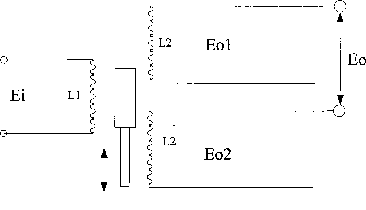
[0044] LVDT sensors are usually used as feedback devices for position signals. In the following, in the vertical motion control system of the workpiece table of the scanning projection lithography machine, three LVDT sensors are used as position feedback devices as an example. Specifically, the LVDT sensor signal detection steps are as follows:

[0045] 1. Initialize the phase coarse adjustment register and the phase fine adjustment register to zero.

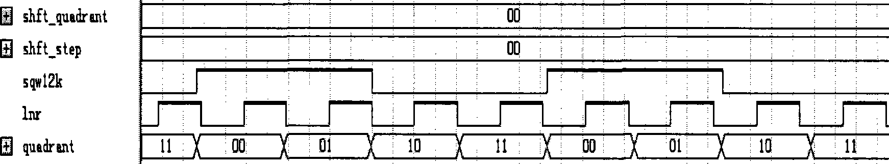
[0046] 2. Use the FPGA to generate a square wave with a frequency of 12KHz, and pass through a second-order low-pass filter to obtain a sine wave with a frequency of 12KHz. Of course, this frequency can be changed arbitrarily, and the commonly used frequencies are 2.5KHz and 5KHz.

[0047] 3. After signal conditioning, the sine wave signal is input to the primary coil of the LVDT sensor as the excitation signal of the LVDT sensor.

[0048] 4. Use the first sampling signal generated by the analog-to-digital conversion chip with a...


PUM


Abstract

The invention provides a method for testing an LVDT sensor signal. The method is characterized in that when an output signal is sampled, the sampled signal and an excitation signal are subjected to the clock synchronization; and by performing a rough adjustment and an accurate adjustment for the phase of the excitation signal, finally, four times' sampling of the sampled signal each period can accurately align to zero, a positive peak, zero and a negative peak of the output signal. The technical proposal provided by the method can acquire a sensor location signal by directly testing an output signal without secondary treatments for the output signal such as sorting, filtering and the like, thereby effectively reducing the error caused by the secondary treatments of the signal, and increasing the accuracy of a feedback position signal of the sensor.

Description

technical field [0001] The invention relates to a signal adjustment method of a sensor, in particular to a signal adjustment method of a linear adjustable differential transformer. Background technique [0002] The structure of the linear variable differential transformer (LVDT) is as follows: figure 1 As shown, it consists of a primary coil winding and two secondary coil windings. Its working principle is: when the ferromagnetic core is dragged along its interior by a non-ferromagnetic rod connected to the moving part of the detection, the primary coil The electromagnetic mutual inductance with each of the two secondary coils changes. When the primary coil is powered with AC voltage, each secondary coil induces an equal voltage when the ferromagnetic core is in the center position. As the core moves off-center, the voltage on one of the secondary coils gradually increases, while the voltage on the other secondary coil decreases, while the absolute change in voltage on bot...

Claims


Application Information

Patent Timeline
Patent Type & Authority Applications(China)
IPC IPC(8): G01D5/14H02P13/00
Inventor 陈锐穆洪德
Owner SHANGHAI MICRO ELECTRONICS EQUIP (GRP) CO LTD
Why Eureka
Try Eureka