Exposure method, exposure apparatus, photomask and photomask manufacturing method

An exposure method and technology of an exposure device, which are applied in the field of photomasks, can solve the problems of difficulty in obtaining the exposure contribution rate of the scanning area, increase in size, etc., and achieve the effects of preventing enlargement and improving utilization efficiency.

Active Publication Date: 2009-02-25
NIKON CORP
View PDF2 Cites 13 Cited by
  • Summary
  • Abstract
  • Description
  • Claims
  • Application Information

AI Technical Summary

Problems solved by technology

However, since the magnification of the projection optical system is increased, the area that becomes redundant with respect to the scanning area will become larger, and the area that is not required for exposure will become larger than the area that is necessary for exposure. Exposure Contribution Ratio

Method used


Image

  • Exposure method, exposure apparatus, photomask and photomask manufacturing method
  • Exposure method, exposure apparatus, photomask and photomask manufacturing method
  • Exposure method, exposure apparatus, photomask and photomask manufacturing method

Examples


Embodiment Construction

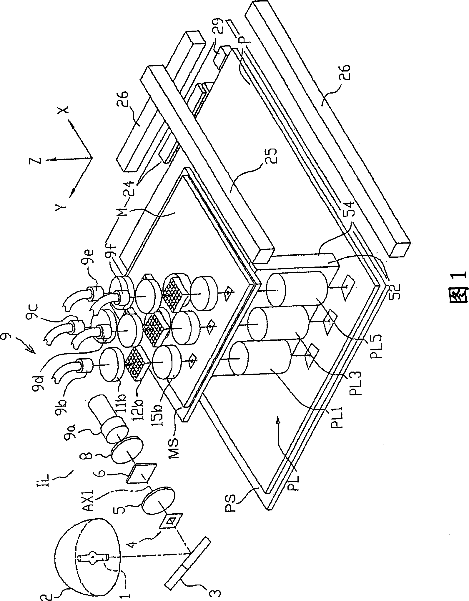
[0084]Hereinafter, an exposure apparatus according to an embodiment of the present invention will be described with reference to the drawings. FIG. 1 is a perspective view showing a schematic configuration of an exposure apparatus according to this embodiment. In this embodiment, an exposure apparatus of a step-and-scan method will be described as an example. In this exposure apparatus, a mask (first object, photomask) M and a flat plate (second object, photosensitive object) P Relatively moves the projection optical system PL composed of a plurality of catadioptric projection optical units PL1, PL3, PL5 and two not-shown projection optical units (hereinafter referred to as projection optical units PL2, PL4). On the flat plate P, the image of the pattern (original image pattern) formed on the mask M is transferred.

[0085] In addition, in the following description, the XYZ rectangular coordinate system shown in each drawing is set, and the positional relationship of each mem...


PUM

PropertyMeasurementUnit
widthaaaaaaaaaa
widthaaaaaaaaaa

Abstract

There is disclosed an exposure method is a method of projecting patterns (M1, M2) of a mask (M) onto a substrate to effect exposure thereof, through a plurality of projection optical units each having an enlargement magnification, and the exposure method comprises: placing the mask (M) having first pattern regions (M1) arranged discontinuously in a positional relation corresponding to the enlargement magnification, and second pattern regions (M2) provided at least in part between the first pattern regions (M1), on the object plane side of the projection optical units; projecting enlarged images of either of the first pattern regions (M1) and the second pattern regions (M2) onto the substrate disposed on the image plane side of the projection optical units to effect exposure thereof; and then projecting enlarged images of the other pattern regions onto the substrate to effect exposure thereof.

Description

technical field [0001] The present invention relates to an exposure method, an exposure device, a photomask and a method for manufacturing the photomask, and in particular to an exposure method using an exposure device for manufacturing microelements such as flat panel display elements such as liquid crystal display elements, An exposure apparatus for exposing by the exposure method, a photomask used in the exposure method, and a method for manufacturing the photomask. Background technique [0002] For example, when manufacturing semiconductor elements or liquid crystal display elements, etc., it is used to project the pattern of the mask (reticle, photomask, etc.) onto a flat plate (glass flat plate or semiconductor) coated with photoresist through a projection optical system. Wafer, etc.) on the projection exposure device. Previously, a projection exposure device (stepper, stepper) that exposes the pattern of each reticle to each shot area on the flat plate at the same ti...

Claims


Application Information

Patent Timeline
Patent Type & Authority Applications(China)
IPC IPC(8): H01L21/027G03F1/08G03F7/20G03F1/68G03F1/70
CPCG03F7/70216G03F7/70791G03F7/70275G03F7/70491G03F7/7055
Inventor 加藤正纪
Owner NIKON CORP
Why Eureka
Try Eureka