Apparatus and method for measuring two-dimensional small angle based on light beam angle drift dynamic compensation

A measurement device and dynamic compensation technology, applied in the direction of measurement devices, optical devices, instruments, etc., can solve the problems such as the angular drift of the beam is not eliminated, the angle measurement deviation, the image signal is weak, etc., to improve the stability and repeatability. , Improve the angle measurement resolution, improve the effect of anti-interference ability

Inactive Publication Date: 2009-03-04
江苏双聚智能装备制造有限公司
View PDF7 Cites 18 Cited by
  • Summary
  • Abstract
  • Description
  • Claims
  • Application Information

AI Technical Summary

Problems solved by technology

[0016] However, in practical applications, especially from the optical path, mechanical structure and measurement process, it can be seen that the above-mentioned measurement schemes have the following deficiencies: in schemes 1-5, no error compensation or correction method is used, and the angular drift of the beam is measured. It is not eliminated in the process, and finally superimposed on the measurement results to cause angle measurement deviation; although schemes 6-8 adopt different error compensation methods to compensate the laser beam angle drift in real time, they cannot overcome the problem of the photoelectric autocollimator itself during the measurement process. The angle measurement error caused by the angle shake is not suitable for the application of two-dimensional angle measurement of a series of measuring points by moving the photoelectric autocollimator, which directly limits the application range of the photoelectric autocollimator. The insufficiency of the scheme itself is also an important problem that cannot be solved in the practical application of the current photoelectric autocollimator
In addition, the reflective surface of the measurement object of the autocollimator should not be too small (for example, the diameter of the measured surface of the ELCOMAT 3000 autocollimator should not be less than 7mm), otherwise most of the parallel light will not be reflected back to the autocollimator. The image signal received by the CCD image sensor is too weak to complete the angle measurement, which is also an important defect of the photoelectric autocollimator

Method used


Image

  • Apparatus and method for measuring two-dimensional small angle based on light beam angle drift dynamic compensation
  • Apparatus and method for measuring two-dimensional small angle based on light beam angle drift dynamic compensation
  • Apparatus and method for measuring two-dimensional small angle based on light beam angle drift dynamic compensation

Examples


Embodiment 1

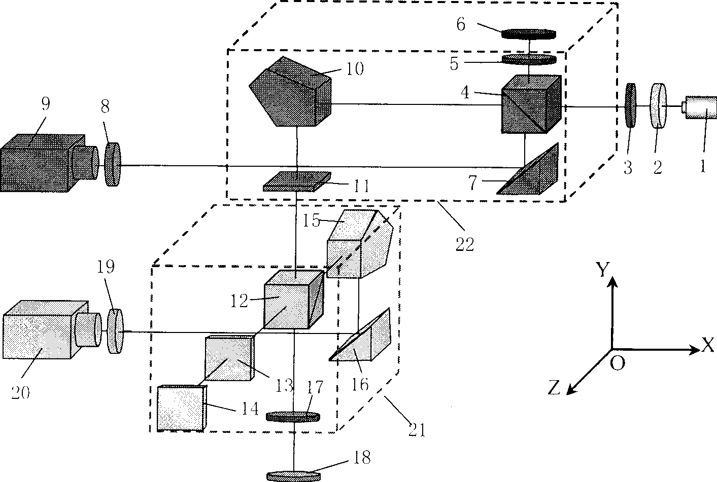
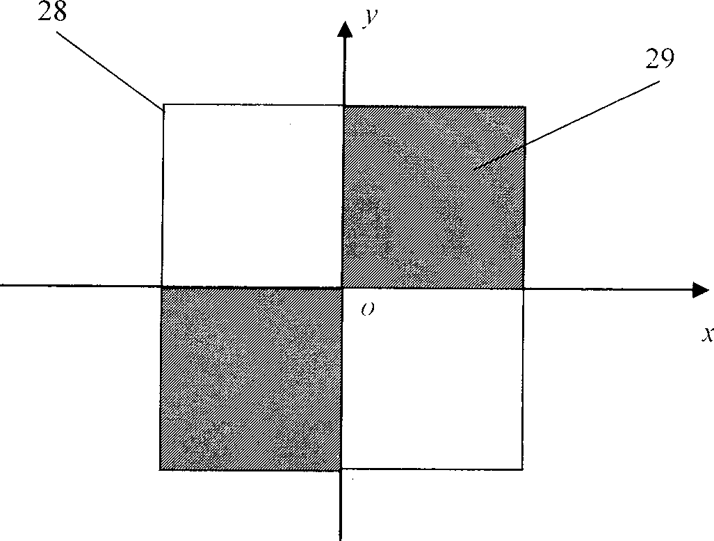
[0083] Such as figure 1 As shown, first adjust the beam splitter 4 and the polarization beam splitter 19, so that the measurement and reference light spots received by the CCD image sensors 9 and 20 are completely separated, see Fig. The light spots received by the CCD image sensor overlap and cannot be accurately positioned. After the adjustment is completed, the beam splitter 4 and the polarization beam splitter 12 should be fixed, and the two are no longer adjusted during the measurement process. The collimated beam emitted by the linearly polarized He-Ne laser 1 is vertically incident on the two-dimensional phase plate 2 to generate a diffracted collimated beam; Reflected by the reflection environment 6, it is incident on the beam splitter 4 through the linear polarizer 5 again, the transmitted light beam is reflected by the plane mirror 7, and is received by the CCD image sensor 9 after passing through the Fourier lens 8, and the minimum value coordinate of the light spot...

Embodiment 2

[0090] see Figure 7 , the plane reference mirror 6 can also adopt a right-angle prism 27, and the measurement and reference beam changes caused by angle drift in the radial angle measurement unit 22 can be found in Figure 8 , the radial angle measurement error caused by beam angle drift is a differential mode signal, and other components and working principles in this embodiment are the same as those in Embodiment 1. For radial angle measurement, the radial angle measurement error caused by angular drift can be dynamically compensated by summing the minimum displacement of the measurement spot and the reference spot, namely:

[0091] θ R =(d MR +d RR ) / (2f)

[0092] Where: θ R is the small angle change along the radial direction at the measuring point; d MR , d RR Be respectively the displacement of radial angle measurement unit 21 and reference signal reference on CCD image sensor 9, f is the equivalent focal length of Fourier lens 8; In this case, the propagation of...

Embodiment 3

[0094] Such as Figure 6 As shown, the linearly polarized He-Ne laser uses a semiconductor laser, and is incident on the two-dimensional phase plate 2 after being collimated and thinned by a single-mode fiber collimating system. The other components and working principles of this embodiment are the same as those of Embodiment 1. .


PUM


Abstract

The invention discloses a two-dimensional small angle measuring device and a method based on light beam angle floating state compensation, belonging to the precision instrument production and precision testing and measuring technical field. The tangential angle measuring unit and the radial angle measuring unit of the instrument are arranged respectively in an orthogonal plane YOZ and an orthogonal plane XOY, and both comprise a light beam angle floating error compensation light path. For the measuring method, the light beam which returns from a self-testing point and has the information of the two-dimensional angle is adopted. The reflected light beam and transmitted light beam produced by a polarization spectroscope are used as the measuring light beam of the tangential angle measuring unit and the radial angle measuring unit. The invention adopts dynamic light beam angle floating error compensation light path, changes the angle floating amount of the light beam into common mode error, separates in real time and compensates dynamically the angle measuring error caused by light beam angle floating, improves repeatability, stability of the two-dimensional small angle during measuring, and reduces the uncertainty of measurement.

Description

technical field [0001] The invention belongs to the technical field of precision instrument manufacturing and precision testing and measurement, and in particular relates to a two-dimensional small-angle measuring device and method based on dynamic compensation of beam angle drift. Background technique [0002] At present, commonly used methods for small angle measurement (α≤1°, especially within ±10-20arcmin) include laser small angle measuring instrument method, standard optical angle gauge method, circular grating angle measurement method, laser interferometry method, photoelectric automatic Collimator method. Among many measurement methods, the laser self-collimation measurement method makes full use of the advantages of laser, has the characteristics of simple structure and convenient use, and has been more and more widely used in metrology science. The laser self-collimation measurement method uses the directivity of the laser itself, takes the center of the laser lig...

Claims


Application Information

Patent Timeline
Patent Type & Authority Applications(China)
IPC IPC(8): G01B11/26
Inventor 谭久彬郎治国刘俭
Owner 江苏双聚智能装备制造有限公司
Why Eureka
Try Eureka