
Guide-rail injection molding technique of heavy numerically controlled machine

A technology of injection molding technology and heavy-duty CNC machine tools, which is applied in the direction of large-scale fixed members, mechanical equipment, manufacturing tools, etc., can solve the problem that the guide rail molding method is not suitable for large-scale workbenches, etc., so as to save the man-hours of plate processing, improve the molding efficiency, The effect of high bonding strength

Active Publication Date: 2011-09-07
JIER MACHINE TOOL GROUP
View PDF0 Cites 1 Cited by
  • Summary
  • Abstract
  • Description
  • Claims
  • Application Information

AI Technical Summary

Problems solved by technology

Since the injection agent is required to have a certain filling pressure when injecting glue in the injection molding industry, it is necessary to construct a closed cavity with injection holes and air holes. This invention only clarifies the position of the injection holes, how to construct a closed cavity with air holes cavity not covered
In addition, as far as the structure of the current workbench is concerned, the small workbench is the above-mentioned structural form with sliders and slider seats, and its guide rail forming method is not suitable for large workbenches.

Method used


Image

  • Guide-rail injection molding technique of heavy numerically controlled machine
  • Guide-rail injection molding technique of heavy numerically controlled machine
  • Guide-rail injection molding technique of heavy numerically controlled machine

Examples


Embodiment Construction

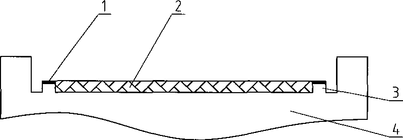
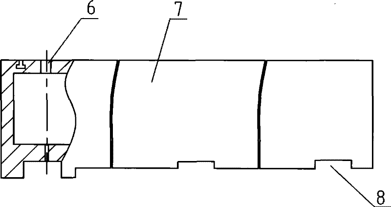
[0033] 1. With reference to the accompanying drawings of the description, in this embodiment, after the assembly accuracy of the bed guide rail 4 meets the requirements and the workbench 7 is processed, a hydrostatic oil chamber 5 is made on the bed guide rail surface, corresponding to the oil chamber to be injected on the bed guide rail. Both sides of the rubber surface 2 are respectively provided with a support edge 3 for supporting the workbench, and the workbench is provided with a plurality of holes 6 for glue injection and exhaust; the process also includes the following steps:

[0034] 1) Seal the oil port with a process plug;

[0035] 2) When making a steel pipe with multiple rows of guide rails connected to each surface to be injected;

[0036] 3) Evenly spray release agent on the contact surface between bed guide rail and adhesive;

[0037] 4) Seal the periphery of the workbench to be injected with a hydrostatic seal level;

[0038] 5) Hoist the workbench on the be...


PUM


Abstract

The present invention discloses a guide way injection molding technology of a heavy numerical control machine tool working table. After the assembly precision of a lathe bed guide way meets the requirements, and a working table is processed, a static press oil cavity is manufactured on the surface of the lathe bed guide way; two sides of the lathe bed guide way corresponding to a face to be injected with glue are respectively provided with a support edge used for supporting the working table; and the working table is provided with a plurality of holes used for injecting the glue and exhausting. The core of the technology lies on constructing a glue-injecting cavity and evenly spraying demoulding agents on the contacted surface of the lathe bed guide way and adhesive when injecting the glue to ensure that a molded guide way is molded at one time. The present invention provides a guide way injection molding technology of the heavy numerical control machine tool working table, which has strong combination affinity and good adhesive bonding performance between a coating layer and metal and the high molding precision and good quality of the guide way and has the characteristic of the high molding efficiency and the long service life of the guide way.

Description

(1) Technical field [0001] The invention relates to a forming process for a guide rail of a workbench of a heavy-duty numerical control machine tool, which belongs to the technical field of guide rail forming of a workbench of a numerical control machine tool, and in particular relates to a technique for forming a guide rail through injection molding of a friction-reducing coating. (2) Background technology [0002] At present, as a machine tool, especially a sliding or hydrostatic guide rail pair of a moving part of a heavy-duty CNC machine tool, it is usually made of an adhesive plate, a soft belt, or a guide rail coating copy molding technology. [0003] Adhesive plate technology is a widely used guide rail manufacturing technology. After the plate is processed, it is bonded to the surface of the cast iron guide rail with an adhesive. It must be fastened with a considerable number of screws. After fastening, it is transferred to a large machine tool for finishing the guid...

Claims


Application Information

Patent Timeline
Patent Type & Authority Patents(China)
IPC IPC(8): F16B11/00B23Q1/03B29C45/14B23Q1/01B29C45/17
Inventor 孙永年贾会述马旭升王凤利周韬
Owner JIER MACHINE TOOL GROUP
Learn More