Wireless communication device
A technology of wireless communication devices and antennas, which is applied to connection devices, antennas, waveguide devices, etc., and can solve problems such as increased influence and reduced antenna efficiency
- Summary
- Abstract
- Description
- Claims
- Application Information
AI Technical Summary
Problems solved by technology
Method used
Image
Examples
Embodiment approach 1
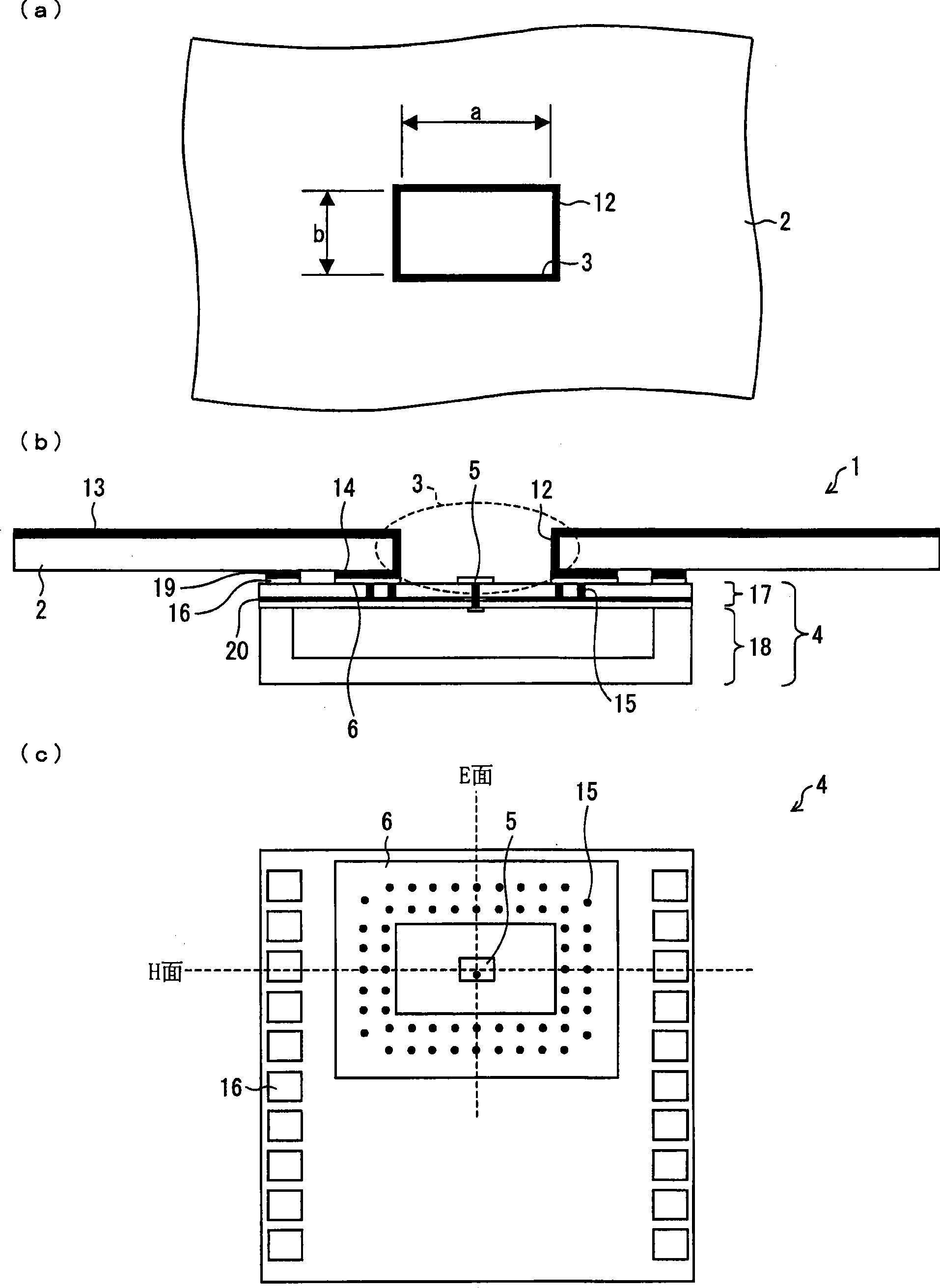
[0022] figure 1 is a diagram showing the configuration of the wireless communication device 1 according to Embodiment 1; figure 1 (a) is a plan view showing the mounting board 2 provided in the wireless communication device 1; (b) is a cross-sectional view showing the wireless communication device 1; Floor plan of module 4.
[0023] figure 1 (c) is a view of the integrated antenna module 4 viewed from the direction of the antenna plane. exist figure 1 In (a), dimensions a and b of the through-hole 3 of the mounting substrate 2 are shown.
[0024] The wireless communication device 1 includes a mounting substrate 2 . A through-hole 3 having a rectangular cross section is formed in the mounting substrate 2 . The wireless communication device 1 is provided with an integrated antenna module 4 which is mounted on the mounting substrate 2 and covers the through hole 3 . On the surface of the integrated antenna module 4 exposed from the through hole 3, a patch antenna 5 for...
Embodiment approach 2
[0046] Figure 5 It is a figure showing the structure of the wireless communication apparatus 1a of Embodiment 2, Figure 5 (a) is a plan view showing the mounting substrate 2a provided in the wireless communication device 1a; Figure 5 (b) is a sectional view showing the wireless communication device 1a; Figure 5 (c) is a plan view showing the integrated antenna module 4a provided in the wireless communication device 1a.
[0047] For convenience of description, components having the same or similar functions as those described in Embodiment 1 above are assigned the same or similar symbols, and detailed description thereof will be omitted. Embodiment 2 differs from Embodiment 1 in that the annular ground piece 6 a and the opening of the through hole 3 a are circular.
[0048] The wireless communication device 1a includes a mounting substrate 2a. A through-hole 3 a having a circular cross section is formed in the mounting substrate 2 a. The wireless communication device 1...
Embodiment approach 3
[0057] Figure 8 It is a diagram showing a configuration in which a mortar-shaped structure 26 and a dielectric lens 25 are arranged in the wireless communication device 1 according to Embodiment 1, Figure 8 (a) is its floor plan, Figure 8 (b) is its cross-sectional view.
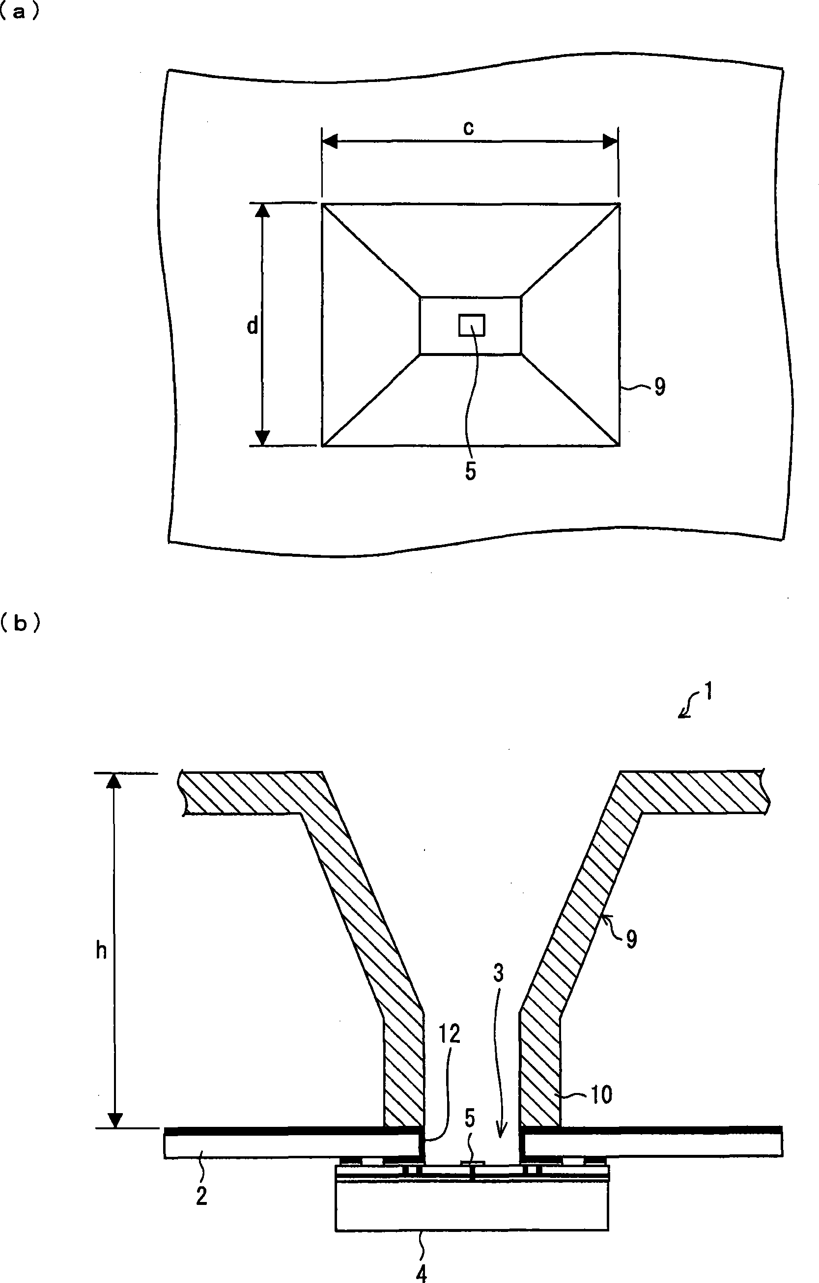
[0058] and figure 2 The horn antenna 9 shown differs in that the Figure 8 In the shown configuration, a mortar-like structure 26 having a lower circular opening 27 and an upper circular opening 28 is disposed on the through hole 3b, and a dielectric lens 25 is disposed on the upper circular opening 28. superior. The depth H of the mortar-like structure 26 is set so that the focal point of the dielectric lens 25 is positioned at the center of the lower circular opening 27 .
[0059] in addition, Figure 8(a) shows an example in which the through-hole 3b is formed with a drill, and the portion corresponding to the short side of the rectangle is formed into a semicircle.
[0060] The diameter of the...
PUM
 Abstract
Description
Claims
Application Information
 - R&D
- Intellectual Property
- Life Sciences
- Materials
- Tech Scout
- Unparalleled Data Quality
- Higher Quality Content
- 60% Fewer Hallucinations
Browse by: Latest US Patents, China's latest patents, Technical Efficacy Thesaurus, Application Domain, Technology Topic, Popular Technical Reports.
© 2025 PatSnap. All rights reserved.Legal|Privacy policy|Modern Slavery Act Transparency Statement|Sitemap|About US| Contact US: help@patsnap.com


