
Slm direct writer

一种空间光调制器、照射方向的技术,应用在光刻领域,能够解决回转时间消耗宝贵时间等问题

Inactive Publication Date: 2009-03-11
MICRONIC LASER SYST AB
View PDF3 Cites 1 Cited by
  • Summary
  • Abstract
  • Description
  • Claims
  • Application Information

AI Technical Summary

Problems solved by technology

[0012] The increased turnaround time also consumes valuable time required for the recording itself

Method used


Image

  • Slm direct writer
  • Slm direct writer
  • Slm direct writer

Examples


Embodiment Construction

[0024] The following detailed description is made with reference to the accompanying drawings. The preferred embodiments are described to illustrate the invention, not to limit the scope of the invention, which is defined by the claims. Those skilled in the art will recognize many equivalent modifications from the following description.

[0025] Furthermore, the preferred embodiment is described with reference to an analog SLM, ie greater than or equal to one gray level between on and off. It will be clear to those skilled in the art that there are cases where other SLMs than analog SLMs are equally suitable; for example, digital SLMs like the Digital Micromirror Device (DMD) made by Texas Instruments. Still further, the preferred embodiment is described with reference to an excimer laser source. It should be clear to those skilled in the art that the method according to the present invention can use pulsed electromagnetic radiation sources other than excimer lasers, such as...


PUM


Abstract

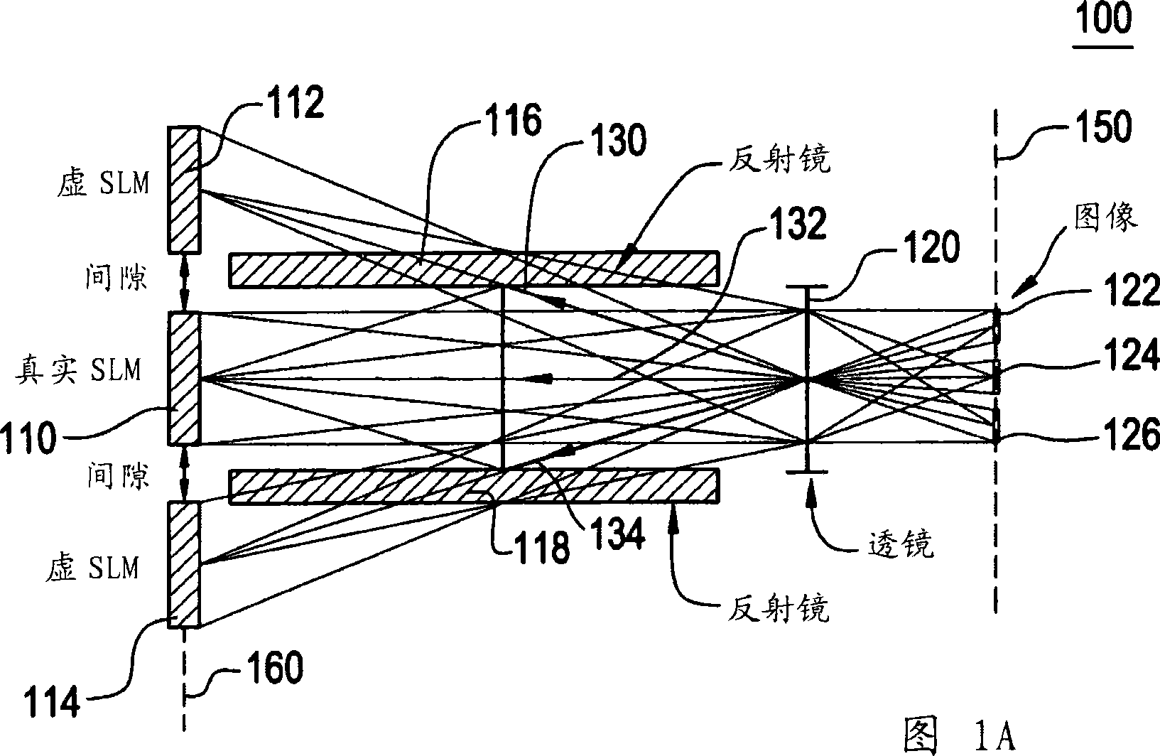
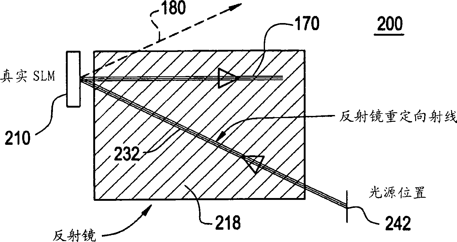
The present invention relates to an apparatus ( 100 ) for patterning a workpiece arranged at an image plane and sensitive to electromagnetic radiation, comprising a source (142)emitting electromagnetic radiation onto an object plane (160) and at least two spatial light modulators each comprising numerous of object pixels adapted to receive said electromagnetic radiation at said object plane and to relay said electromagnetic radiation toward said workpiece, wherein said electromagnetic radiation is split into at least two beams which will impinge on different spatial light modulators, by a beam splitting device arranged at an optical plane between said spatial light modulators and an illuminator pupil or a conjugate optical plane. The invention also relates to a method for patterning a workpiece with a plurality of spatial light modulators.

Description

technical field [0001] The present invention relates to lithography, and in particular to a method and apparatus suitable for direct writing of patterns using at least one spatial light modulator (SLM). Background technique [0002] Modern UV-lithography is exploring new highly parallel recording concepts. Spatial light modulation with optical MEMS devices offers the possibilities described above. The SLM chip consists of a DRAM-like CMOS circuit with millions of individually addressable pixels on top. These pixels are deflected due to electrostatic force differences between the mirror elements and the address electrodes. A pattern generator using an SLM is described in US6373619, assigned to the same assignee as the present invention. Briefly, US6373619 describes a small field stepper which exposes a sequence of SLM images. The workpiece is placed on a continuously moving step, and a pulsed electromagnetic radiation source (which can be a pulsed laser, a flash lamp, a f...

Claims


Application Information

Patent Timeline
Patent Type & Authority Applications(China)
IPC IPC(8): G03F7/20
CPCG03F7/70208G03F7/70275G03F7/70291G03F7/2051G03F7/2059G03F7/70383
Inventor 托马斯·洛克
Owner MICRONIC LASER SYST AB
Learn More