Feeding structure of housing with antenna

A shell and antenna technology, applied in the field of feed structure

Active Publication Date: 2009-03-11
NISSHA PRINTING COMPANY
View PDF1 Cites 23 Cited by
  • Summary
  • Abstract
  • Description
  • Claims
  • Application Information

AI Technical Summary

Problems solved by technology

[0010] The present invention is completed considering the problems of the above-mentioned existing antennas for small portable devices, and its purpose is to provide a housing that is not easily affected by metal parts Feed structure with an antenna case that can feed power to a planar antenna by attaching a planar antenna on the surface of the body inconspicuously without providing a through-hole that would cause an unsightly appearance

Method used


Image

  • Feeding structure of housing with antenna
  • Feeding structure of housing with antenna
  • Feeding structure of housing with antenna

Examples


Embodiment 1

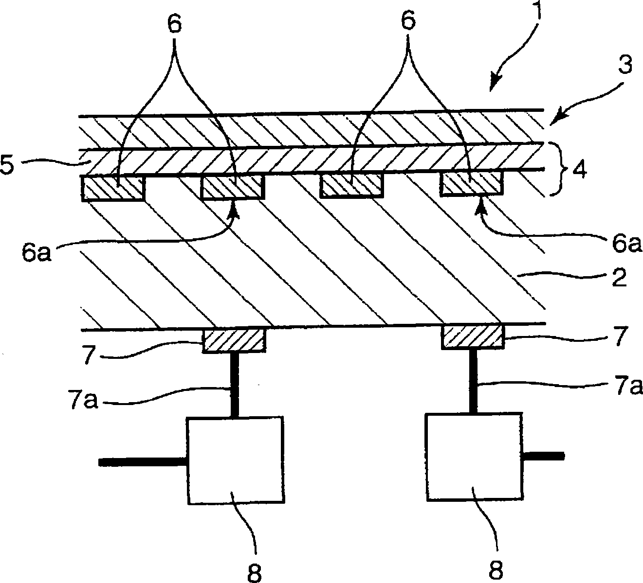
[0109] First, a 50 micron (μm) thick PET film is used as the film base material 5, and an 18 micron thick copper foil is formed on one side as a conductive layer, and the copper foil is formed in the shape of a helical antenna for RFID by photolithography. Carry out pattern making, form planar antenna 6, thereby obtain antenna film 4 (with reference to figure 1 ).

[0110] Also, a decorative layer was formed on one side of a transparent acrylic film having a thickness of 50 microns by gravure printing to obtain a decorative film 3 .

[0111] Next, the antenna film 4 is adhered to the decorative layer side of the decorative film 3 with a transparent adhesive to form an inlaid film, and the inlaid film is preliminarily processed according to the molding metal mold used to form the outer surface shape of the housing 2. take shape.

[0112] Here, when bonding the decorative film 3 and the antenna film 4, the planar antenna 6, the film base material 5, the decorative layer, and ...

Embodiment 2

[0118] First, a 50 micron (μm) thick PET film is used as the film base material 5, and an 18 micron thick copper foil is formed on one side as a conductive layer, and the copper foil is patterned in the shape of a helical antenna by a printing method. , forming a planar antenna 6, thereby obtaining an antenna film 4 (refer to Figure 5 ).

[0119] A decorative film 3 was obtained by forming a decorative layer on one side of a transparent polycarbonate film having a thickness of 50 micrometers by gravure printing.

[0120] Next, the antenna film 4 is adhered to the decorative layer side of the decorative film 3 with a transparent adhesive to form an inlaid film, and the inlaid film is preformed according to the shape of the outer wall surface forming the housing 2 . The bonding between the decorative film 3 and the antenna film 4 is the same as that in the first embodiment above.

[0121] Next, using a molding die capable of molding a case 2 with a thickness of 1 mm, the inse...

Embodiment 3

[0126] First, a 25-micron (μm) thick polyimide film is used as the film base material 5, and an 18-micron thick copper foil is formed on one side as a conductive layer, and the helical antenna is pressed by an etching method based on a printed resist. The shape of the copper foil is patterned to form a planar antenna 6, thereby obtaining the antenna film 4 (refer to Figure 5 ).

[0127] Also, a decorative layer was formed on one side of a transparent acrylic film having a thickness of 50 microns by gravure printing to obtain a decorative film 3 .

[0128] Next, the antenna film 4 is adhered to the decorative layer side of the decorative film 3 with a transparent adhesive to form an inlaid film, and the inlaid film is preformed according to the shape of the outer wall surface forming the housing 2 .

[0129] Next, using a molding die capable of molding a case 2 with a thickness of 1 mm, the insert film is inserted into the molding die, the mold is closed, and polycarbonate re...


PUM


Abstract

A feeding structure of a housing with an antenna, in which a flat antenna can be attached inconspicuously to the outer surface of the housing which is hard to be affected by a metal component and power can be supplied to the flat antenna without providing a through hole causing inferior appearance. The feeding structure of the housing with an antenna comprises a housing 2, a decorative film 3 covering at least a part of the outer wall face of the housing 2, a flat antenna 6 held between the outer wall face of the housing 2 and the decorative film 3, and an electrode 7 provided on the inner wall face of the housing 2. In the feeding structure, a capacitor is formed by arranging a feeding part 6a of the flat antenna 6 and the electrode 7 opposite to each other in both faces of the housing 2 and power transmission and communication are performed in a noncontact manner for the flat antenna 6 on the outside of the housing 2 from the inside of the housing 2 by connecting an inductor 8 with the electrode 7.

Description

technical field [0001] The present invention relates to power transmission using an antenna provided on the outer surface of a casing of a small portable device such as a portable phone, a PDA (Personal Digital Assistance), an MP3 (MPEG-1 Audio Layer 3: an international standard for sound information compression) player, etc. and feed structure with antenna housing for signal transmission. Background technique [0002] Of course, an antenna is needed in a portable phone, and an antenna is also needed when a communication function is added to a small portable device such as a PDA or an MP33 player. into the housing of the portable device. [0003] However, there are metal protective boxes and ground plates (planar bodies composed of conductors that reflect electromagnetic waves) to eliminate the influence of unwanted electromagnetic radiation inside the housing. The existence of these metal parts significantly damages the communication function of the antenna. [0004] In o...

Claims


Application Information

Patent Timeline
Patent Type & Authority Applications(China)
IPC IPC(8): H01Q1/38H01Q1/40H01Q1/50H01Q7/00H01Q9/16
CPCH01Q9/27H01Q1/44H01Q1/40H01Q1/38H01Q7/00
Inventor 石桥达男奥村秀三
Owner NISSHA PRINTING COMPANY
Why Eureka
Try Eureka