
Flexible color changing neon lamp for simple thin LED

A technology of light-emitting diodes and diodes, which is applied in the direction of semiconductor devices, light sources, electric light sources, etc. The effect of saving material cost and production cost, volume and weight reduction

Inactive Publication Date: 2009-03-18
田德华
View PDF0 Cites 11 Cited by
  • Summary
  • Abstract
  • Description
  • Claims
  • Application Information

AI Technical Summary

Problems solved by technology

Some of the neon lights currently used are glass neon lights. The disadvantages of this kind of neon lights are: the glass is fragile, unsafe, and has a short life, so its application is greatly limited, and it has a tendency to be slowly replaced by new products; The other part is the LED flexible color-changing neon light that has gradually become the mainstream. This neon light is provided with several light-emitting diodes in a flexible housing. These light-emitting diodes are connected in series or in parallel and powered by a rectified DC power supply. By adjusting the strength of the current, the light-emitting color of the light-emitting diode or the color of the outsourcing material of the light-emitting diode, etc., the effect of glass neon lights in which each part of the light-emitting diodes emit light of different strengths and colors in different time periods is achieved. This kind of neon light is flexible. Strong, widely used, long life, safety and other advantages, so it has been widely used
For lateral discoloration and color mixing, that is, the discoloration and color mixing of bulbs of different colors, this structure has great defects: the effect of lateral discoloration and color mixing is extremely poor, the color is impure, there are spots, and the brightness is too low (because the height is too high) ),and many more
Therefore, all the current diode neon lamps have an undisputed defect, that is, the diode bulb is used as the light source. Since the width (big) and the height of the diode bulb are relatively wide (big), the width and height of the entire product cannot be reduced, thus It makes its volume and weight large and not easy to bend. It is inconvenient to apply in many occasions that require small width, low height, light weight, and many bends, which is not conducive to the healthy development of the diode neon light industry.
[0005] At the same time, diode bulbs also have great defects in the use of light sources. Because its shell is transparent or translucent, its light will radiate around, while diode neon lights use the light source above it, so diodes A lot of light around the bulb is wasted because it cannot be projected into people's sight, forming a waste of energy, which does not meet the national energy conservation (environmental protection) policy; Small, resulting in unsatisfactory color mixing effect
[0006] Finally, in the existing integrated diode neon lights, the three welding points on the same side of the PCB board are all located on the same straight line, and they are all spot welding on the panel. Due to the adjacent distance of the three welding points The solder joints are very small and the solder joints are large (due to the large amount of welding, it is generally impossible to perform delicate welding), so it is easy to produce creepage phenomenon, that is, a certain circuit conduction phenomenon occurs between adjacent solder joints, so that The voltage at both ends of the corresponding diode is reduced, resulting in insufficient luminous brightness or impure color mixing, thereby reducing the quality of the entire product

Method used


Image

  • Flexible color changing neon lamp for simple thin LED
  • Flexible color changing neon lamp for simple thin LED
  • Flexible color changing neon lamp for simple thin LED

Examples


Embodiment Construction

[0028]Below in conjunction with accompanying drawing, the present invention will be further specifically described:

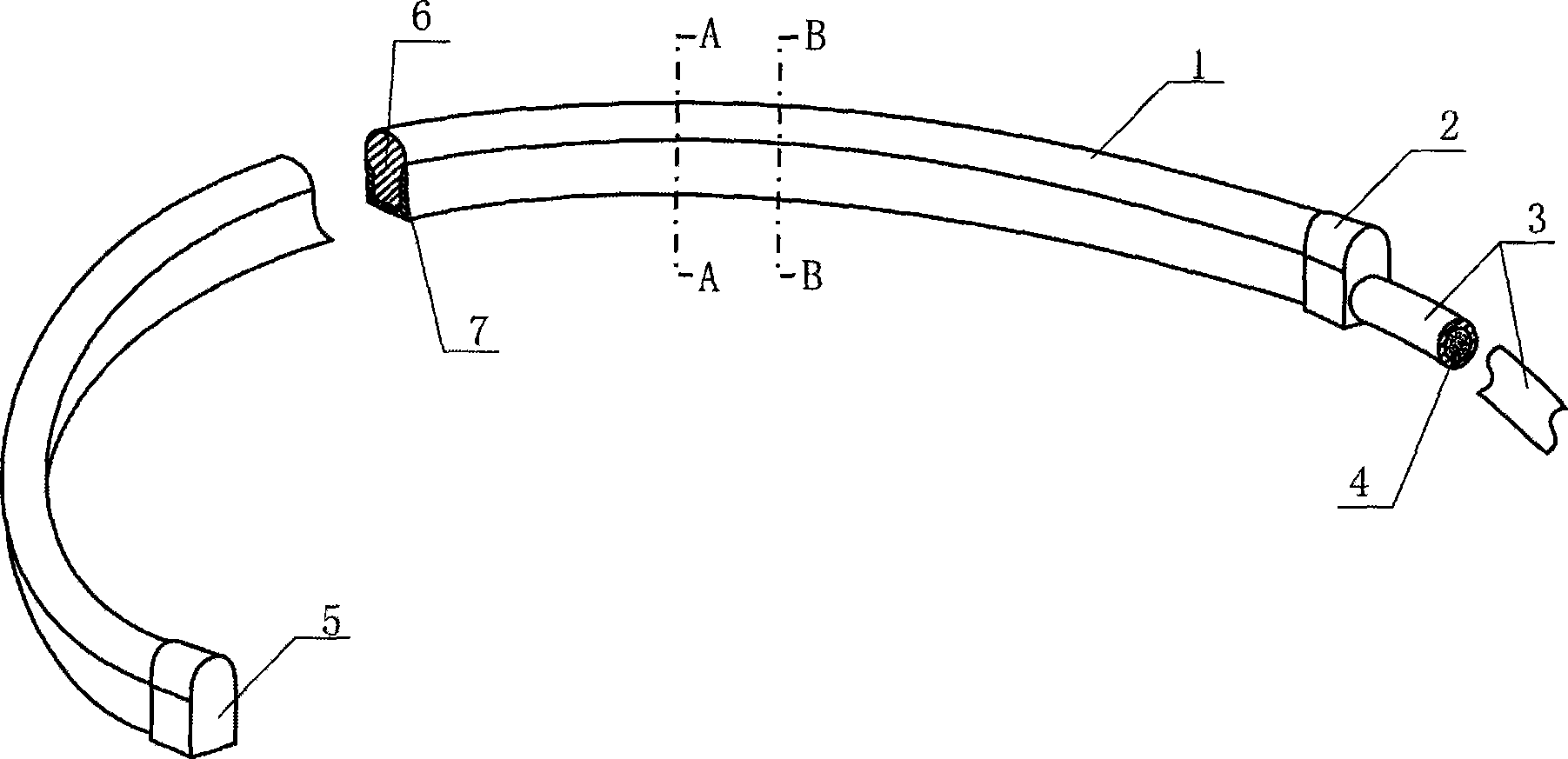
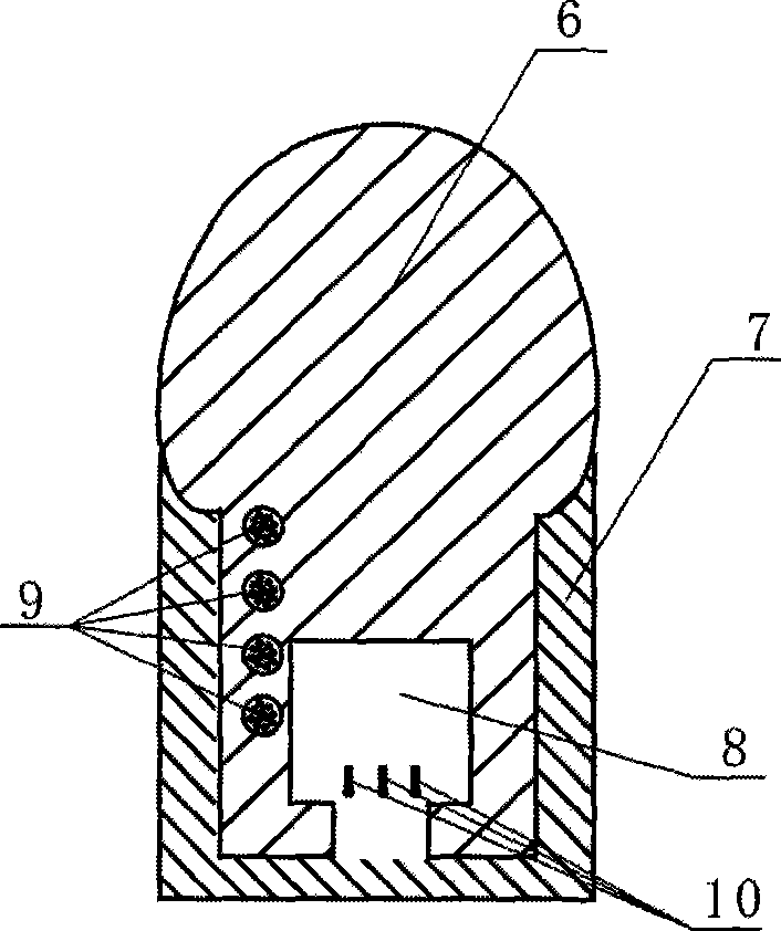
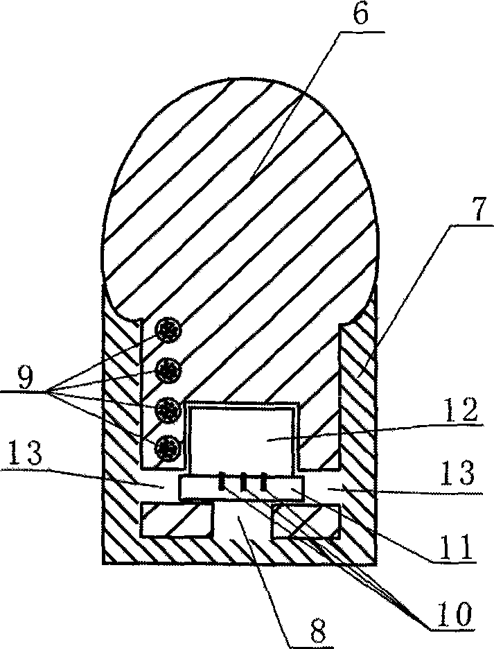
[0029] Such as figure 1 , figure 2 and image 3 as shown, figure 2 It is a cross-sectional view of a part of the lamp tube 1 located between two adjacent diode light emitting units, image 3 It is a cross-sectional view of a part of the lamp tube 1 within the scope of the diode light emitting unit. The present invention includes a core wire 6, a diode light emitting device, a copper strand 9, an opaque coating layer 7, and a DC power supply device. Such as Figure 4 As shown, the figure only shows the structure of one of the core wires 6, combined with figure 2 , image 3 and Figure 4 , the core wire 6 is a translucent diffuser, a groove 8 coaxial with the core wire 6 and equal in length is provided under the core wire 6, the diode light-emitting device is installed in the groove 8, and the light-emitting surface of the diode light-emitting unit is u...


PUM


Abstract

The invention discloses a simple and thin light-emitting diode flexible coloring neon light, which comprises a core wire, a diode luminous device, a copper stranded wire, an opaque cladding layer, and a direct current power source device. The diode luminous device is formed by connecting in series a plurality of diode luminous units, the core wire is a semi-transparent astigmatism body, the lower side of the core wire is provided with a groove which is coaxial with the core wire and has the equal length with the core wire, the diode luminous device is arranged inside the groove, and an opening on the lower side of the groove is narrower than a space on the upper side of the groove; and the parts of the core wire positioned on the both sides of the diode luminous device and under the diode luminous device are cladded by the opaque cladding layer. With a primary formation process, the astigmatism body and the core wire are combined into one, the copper stranded wire is directly packaged in the core wire and the diode luminous device is directly arranged in the core wire, thereby obviously reducing the width, the height, the volume and the weight of the whole product, greatly expanding the application range of the diode neon light, reducing the process and lowering the cost.

Description

technical field [0001] The invention relates to a neon lamp, in particular to a simple thin light-emitting diode flexible color-changing neon lamp with brilliant colors, wide application, small size and light weight, belonging to the production field of neon lamps. Background technique [0002] With the acceleration of urban modernization and the improvement of people's living standards, neon lights, as a fascinating lighting device, have been widely used in entertainment venues, exterior renderings, advertising and family life, and their colorful light sources make people feel refreshed. Some of the neon lights currently used are glass neon lights. The disadvantages of this kind of neon lights are: the glass is fragile, unsafe, and has a short life, so its application is greatly limited, and it has a tendency to be slowly replaced by new products; The other part is the LED flexible color-changing neon light that has gradually become the mainstream. This neon light is provid...

Claims


Application Information

Patent Timeline
IPC IPC(8): F21S4/00F21V5/08F21V23/00F21V15/02F21W121/00F21Y101/02
CPCF21S4/007F21Y2101/02F21S4/26F21Y2115/10
Inventor 田德华
Owner 田德华
Learn More