2D-3D convertible stereo display device

A technology for stereoscopic display devices and display panels, applied in stereoscopic systems, static indicators, optics, etc., can solve the problems of long response time, difficult process, and inability to control each pixel independently, and achieve fast conversion speed and difficult implementation low effect

Inactive Publication Date: 2009-03-18
SHENZHEN SUPER PERFECT OPTICS LTD
View PDF5 Cites 39 Cited by
  • Summary
  • Abstract
  • Description
  • Claims
  • Application Information

AI Technical Summary

Problems solved by technology

[0004] Due to the very high precision requirements of the microlens array and the non-flat surface, this process of plating a conductive thin layer or a gradient electrode layer on the surface of the microlens array is very difficult, and it is difficult to ensure the accuracy of the microlens array after the conductive thin layer is plated. Accuracy; and the voltage is applied on the conductive thin layer between the microlens array and the transparent plane plate to form an electric field, the distance of the electric field is large, and the electric field intensity is very small under the same supply voltage, the microlens array and the transparent plate between The time for the liquid crystal director to align with the electric field and the time for the liquid crystal director to return to the original alignment position when the electric field is withdrawn are very long, resulting in a very long response time for the device to switch between 2D and 3D, causing discomfort to the audience's eyes
Moreover, the above-mentioned existing 2D-3D conversion cannot realize independent control of each pixel point, cannot display stereoscopic and planar images to the audience at the same time, let alone dynamically display stereoscopic or planar images, and the functions and effects of the display are not satisfactory.

Method used


Image

  • 2D-3D convertible stereo display device
  • 2D-3D convertible stereo display device
  • 2D-3D convertible stereo display device

Examples


Embodiment (1

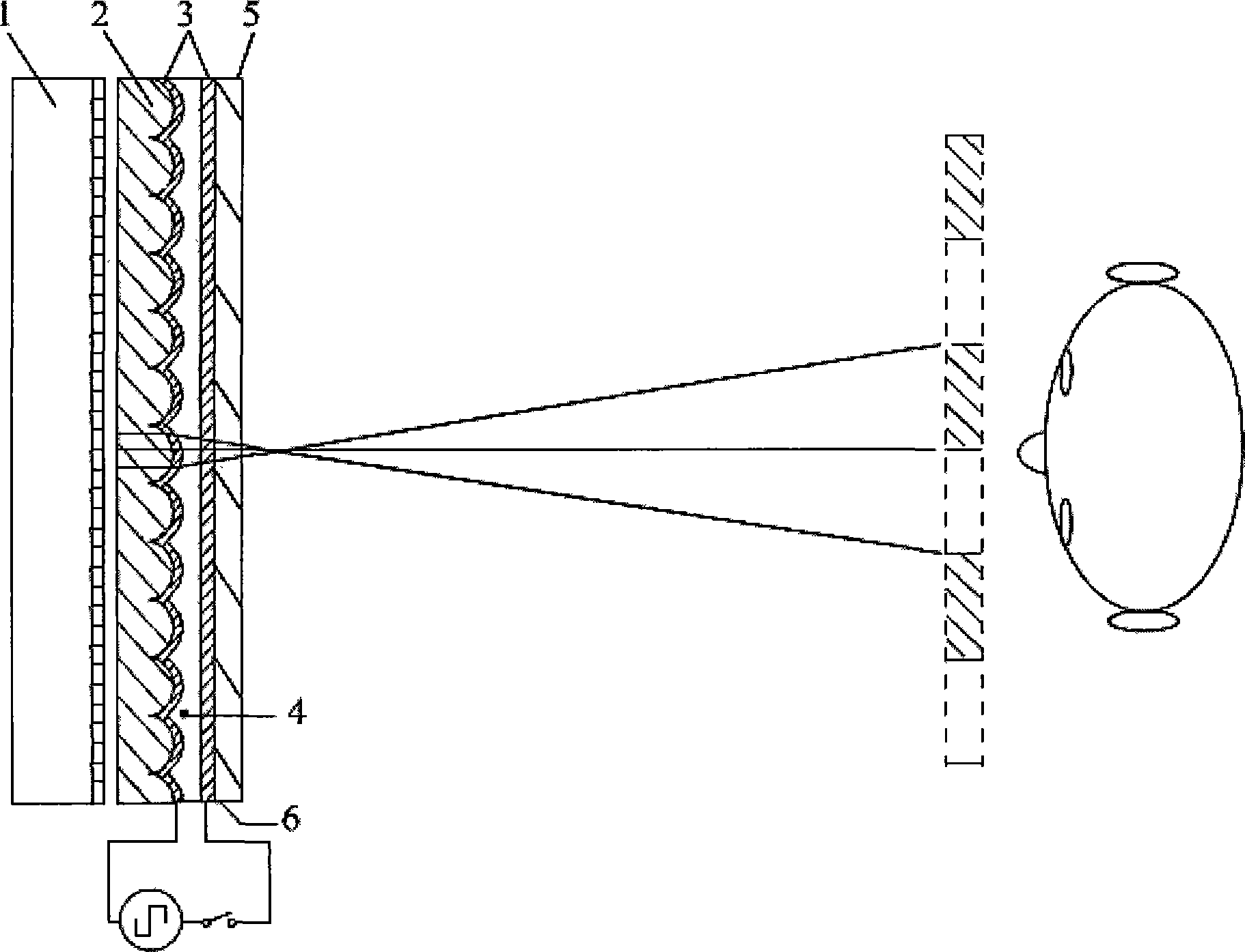
[0035] Embodiment (1): Figure 6 It is the structure and optical path diagram of the stereoscopic display device of the present embodiment, in which the stereoscopic display device includes: a display panel 10 for providing images, and a polarizer for selectively not rotating or rotating the polarization direction of the light provided by the display panel 10 by 90 degrees. A light conversion device, and a lens assembly composed of a single-refraction index lens and a double-refraction index lens, are used to transmit the provided image in 2D mode, and divide the incident image into a right-eye image and a left-eye image in 3D mode. The polarized light conversion device includes a thin film transistor circuit 11c (the distance between the display panel 10 and the thin film transistor circuit 11c is only schematic, mainly for marking the polarization direction of the light), as a driving electrode (equivalent to the existing TFT Display electrode in the display) ITO glass 11a, ...

Embodiment (3

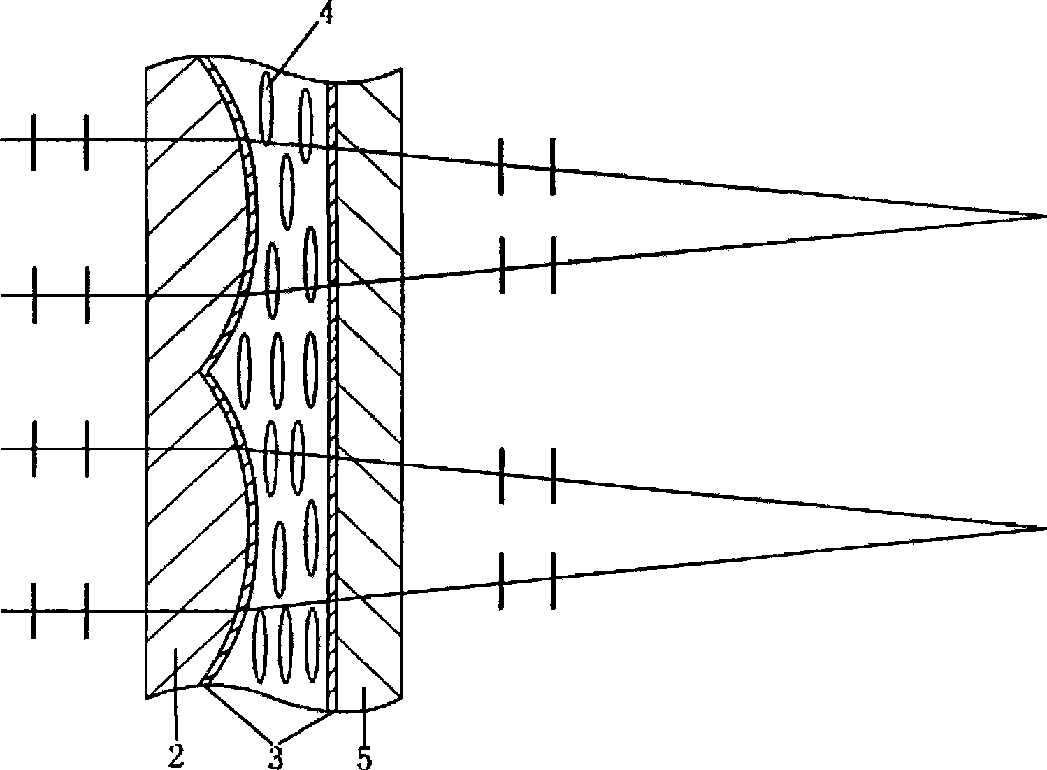
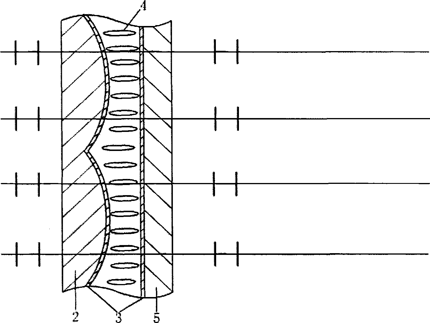
[0046] Embodiment (3): Figure 8 It is the structure and light path diagram of the stereoscopic display device of this embodiment, the stereoscopic display device also includes in the figure: a display panel 10 (not shown in the figure) that provides images, and is used for selectively polarizing the direction of light provided by the display panel 10 Non-rotating or 90-degree polarized light conversion devices, and lens components composed of single-refractive-index lenses and double-refractive-index lenses, the only difference between this embodiment and embodiment (1) lies in the composition of the lens components. In this embodiment, the lens assembly includes a double refraction convex lens 17, a single refraction concave lens 18 and a glass substrate 16, and also includes an orientation layer 12c on the surface of the plane part of the birefringence convex lens 17. The convex lens 17 adopts a birefringence material, usually Select liquid crystal for use, select the optic...


PUM


Abstract

The invention discloses a 2D-3D conversable stereo display device, comprising: a device providing image light, a polarized light converter and a lens component, wherein the device providing image light is used for providing image lights of linear polarization, the polarized light converter is used for controllably transmitting the incident image lights of linear polarization completely or incompletely, or rotating the incident image lights into the polarization light vertical to the incident polarization direction, the emergent light is input to the lens component, the lens component comprises a single-refraction lens and a dual-refraction lens which form a combination lens and both comprise a plane part and a relative curve part, the cure parts of the two lenses are wedged with each other, the combination lens can present a convex lens for one of the two polarization light output by the polarization light converter after rotation or no rotation, and can present a plate lens. The 2D-3D conversable stereo display device can freely realize 2D-3D conversion.

Description

technical field [0001] The invention relates to the field of stereoscopic display, in particular to a device capable of performing 2D or 3D conversion in any area of ​​the screen. Background technique [0002] Humans perceive the depth of objects through the slight difference between what the right and left eyes see, and thus recognize stereoscopic images. This difference is called parallax. Stereoscopic display technology is to create the parallax of the left and right eyes of people through artificial means, and send two images with parallax to the left and right eyes respectively, so that the brain can observe the real three-dimensional objects after obtaining the different images seen by the left and right eyes. a feeling of. There are generally two types of stereoscopic display devices: a slit grating type stereoscopic display device and a microlens array stereoscopic display device. The microlens array stereoscopic display device includes a display panel and a microl...

Claims


Application Information

Patent Timeline
Patent Type & Authority Applications(China)
IPC IPC(8): G02B27/26G02B27/22H04N13/00G02F1/133G02B30/25
Inventor 戈张杨扬
Owner SHENZHEN SUPER PERFECT OPTICS LTD
Why Eureka
Try Eureka